Tony Hebb’s F1D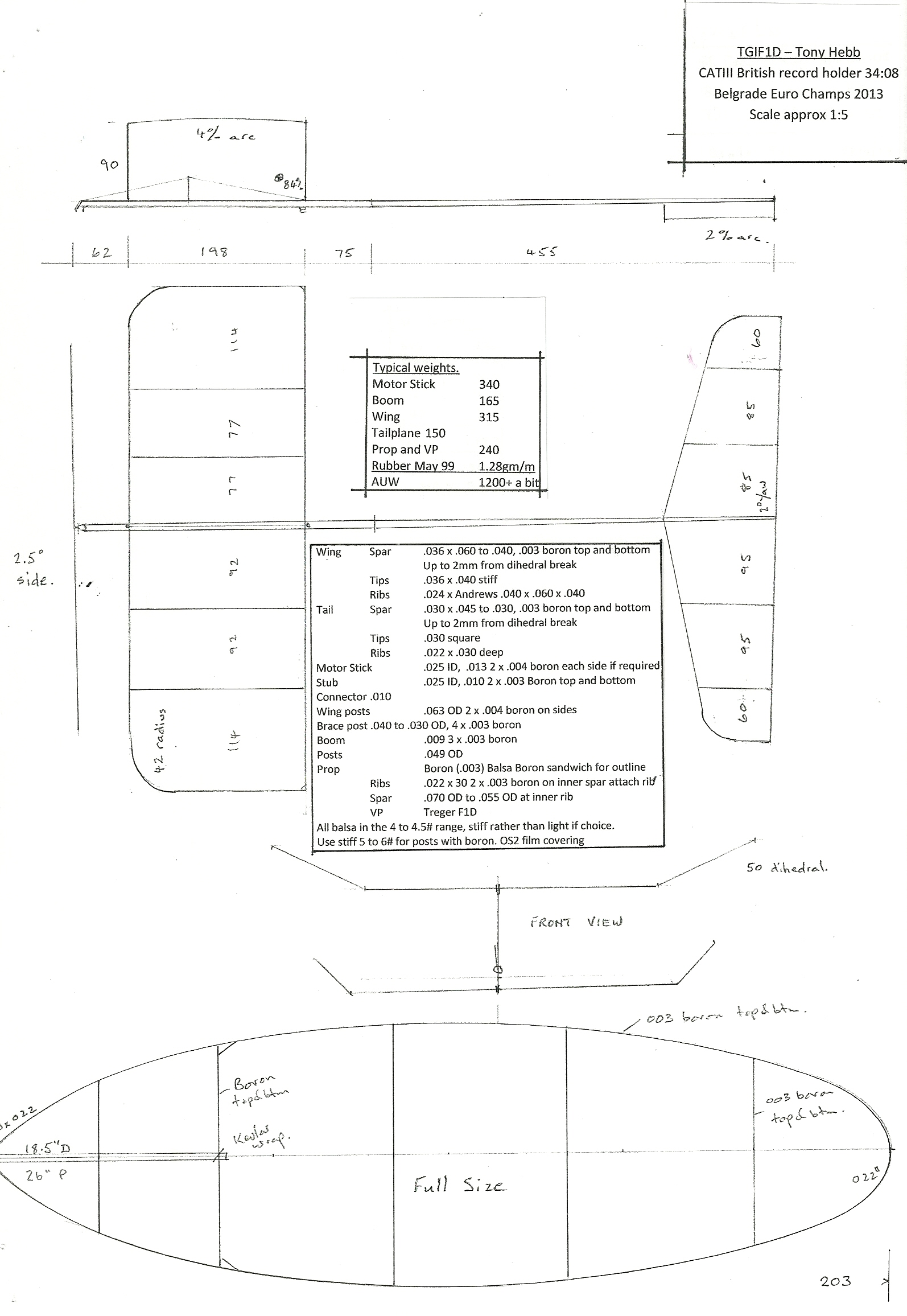 Click here to download a PDF of Tony’s plan.

Indoor flying with Supercaps
We are a group of 6 or 7 indoor flyers in Southern Germany using the new high density capacitors such as the “Green Caps” from Samwha for powering indoor models. The supercaps have a 5 or 10 Farad capacity and weigh about 2 or 3 grams. If one cuts the legs and removes the plastic coating the caps get about 0.3 gms lighter. Principally, one can use the structure of an F1M or F1L with a lighter fuselage, because the extreme torques caused by the rubber band are missing. The structure should weigh about 1.4 gms and be strong enough to bear 5 or 6 gms in total. The coreless 6 mm pager motor with a resistance of 10 or 30 Ohms weighs 1.3 gms and the 1:6.6 or 1:9 gear another0.7 gm. We also tested 4 mm coreless motors that are also usable but the gear with modul 0.2 is more difficult to handle. The 6 mm types show about 50% efficiency, the 4 mm types only 35-40%. Total efficiency of the drive ranges at about 20%, including propeller and gear losses. Depending on the equipment, the ready to fly weights range from 5.0 to 6.2 gms.
The propeller diameters range from 120 to 135 mm and the pitch ranges from 70 to 110 mm depending on the gear ratio. I use blades made from 0.4 mm C-grain with spars from 0.7 mm CF. Other people make their blades from thin plastic (yogurt) cans.
What are the flight times? We started with 1:30 min and now – one year later – we are at 5:30 min. Theoretically, with a medium current of 30 mA, a flight time of max. 6 minutes should be possible. Roland Oehmann flew already 5:40. The green caps with a 2.7 Volts reference value can obviously be loaded up to 3.4 Volts taking no noticable damage. Then, a voltage range from 3.4 to 2.2 Volts is usable. Load times are from 30 to 60 seconds depending from capacity. Note: If the final voltage is reached the current flows another 10 to 20 seconds enhancing the total charge of the cap.
Charging is possible from any power supply that allows for a 3.4 Volts default value. No preresistor is necessary. Some people use a full 4.15 Volts Lithium cell and a silicon diode with the 0.7 Volts gap voltage loss in series. Please mind the high load currents of some Amps in the first seconds. But you can also cut them by presetting an upper current-limit.
Motors and gears come from www.Didel.com
Author: Heinrich Eder, Munich, Germany, eder-h@arcor.de
Pics:
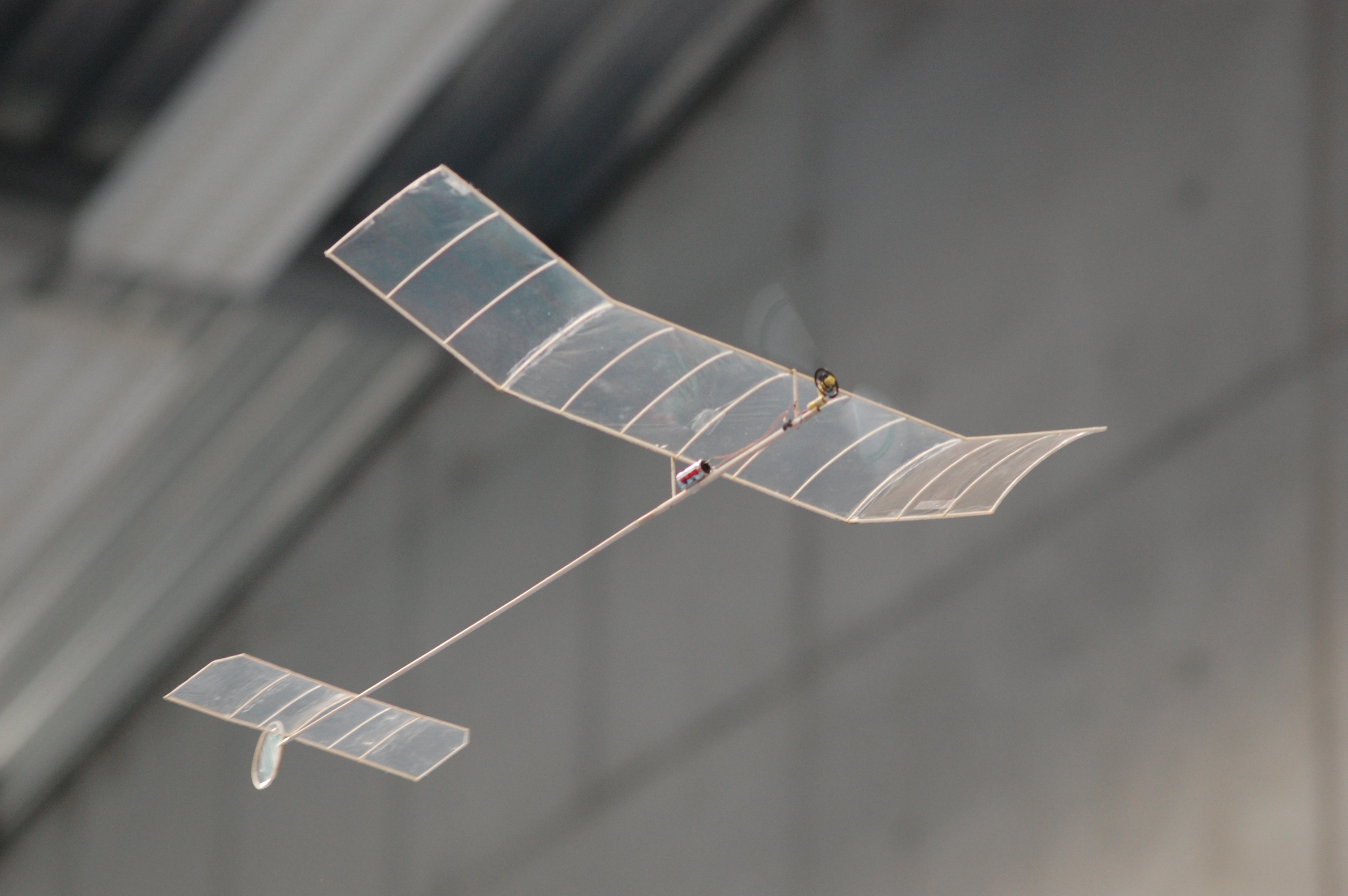
1 The authors “Capino I” driven by a 4 mm coreless motor, gear ratio 1:10 and a 5 Farad Green Cap

2 “Capino 2” is driven by a 6 mm coreless motor 30 Ohm with a 1:9 gear
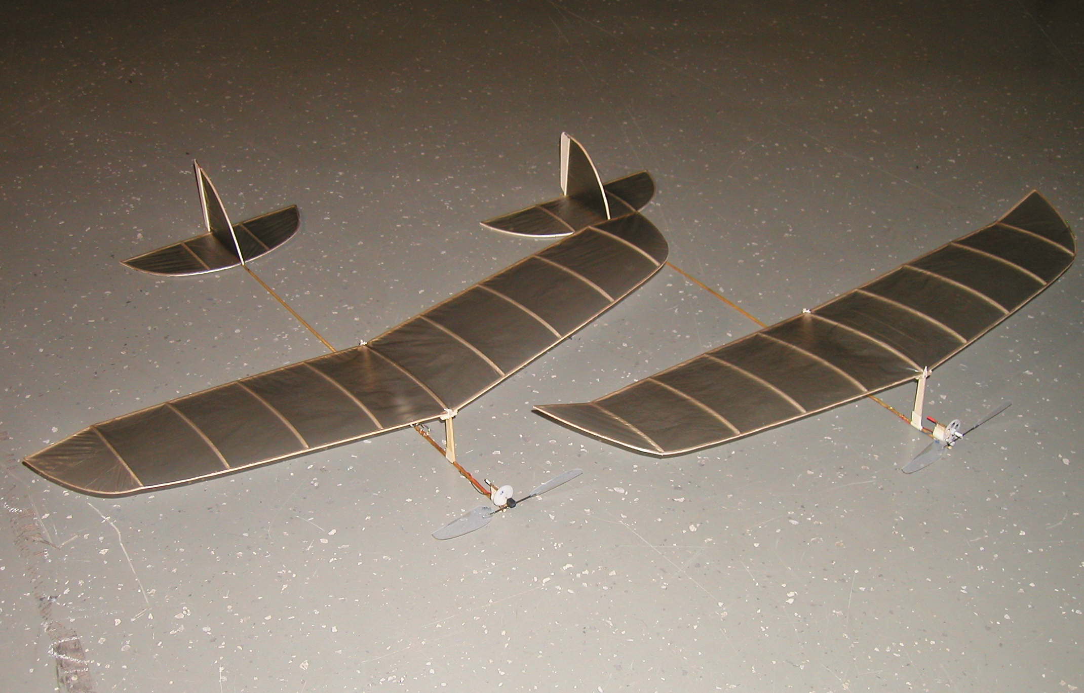
3 The models “Cappy I and Cappy II” from Roland Oehmann, Stuttgart, Germany
LPP Carbon Prop Spar
By Mike Kirda
Recently I built a Limited Penny Plane to compete in the Bong Eagles contest. I’ve been pretty hard on LPP props in the past – Racine Memorial Hall’s ceiling is quite scrubbable, but I still broke my fair share. Determined to avoid this, I built a very robust prop spar: 7# balsa, 0.125″ center tapered to 0.080″ tip.
On my last flight of the day, the plane hit a railing and broke the prop spar while walking down the wall. It was centered on an open door and flew into the next room where many contestants were set up. All had a good laugh as my ‘Korda Wakefield’ continued to bang around the ceiling just out of reach for the next couple of minutes.
I wasn’t very happy to be honest – I kept thinking “Stupid Spar”. I thought back to Kang Lee’s Carbon VP hub and the carbon tube it used and wondered how well it would work…
The carbon tube is very strong and the blades needed less support than I imagined. I built a couple of new props using the carbon tube, trying them out at the next flying session and they worked very well.
One bit about carbon: Be careful around the dust. I use a vacuum to keep it down, plus use a particulate mask if cutting it indoors. Outdoor might be a better option. All cuts are made with a Dremel and diamond cutoff wheel.
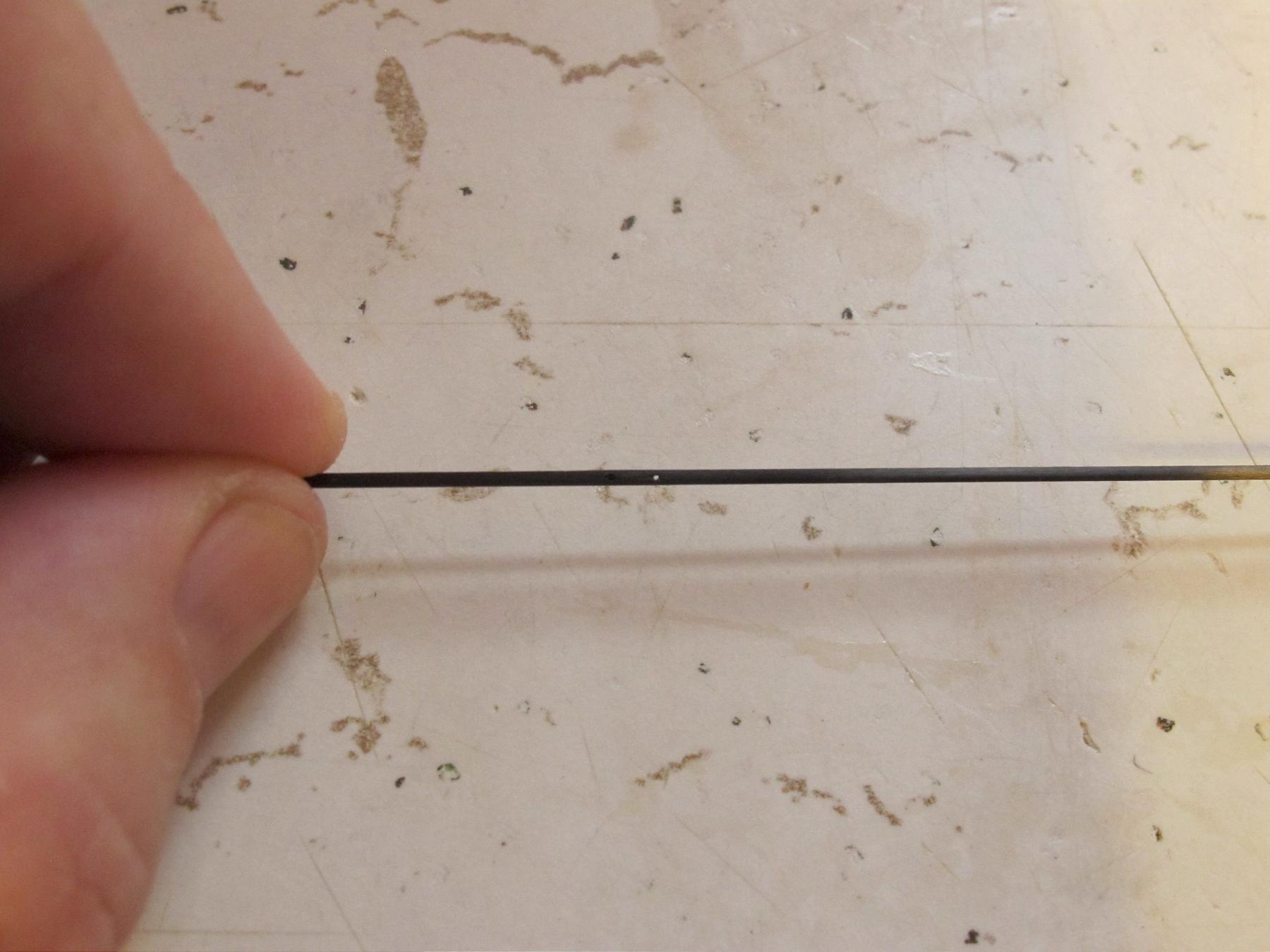
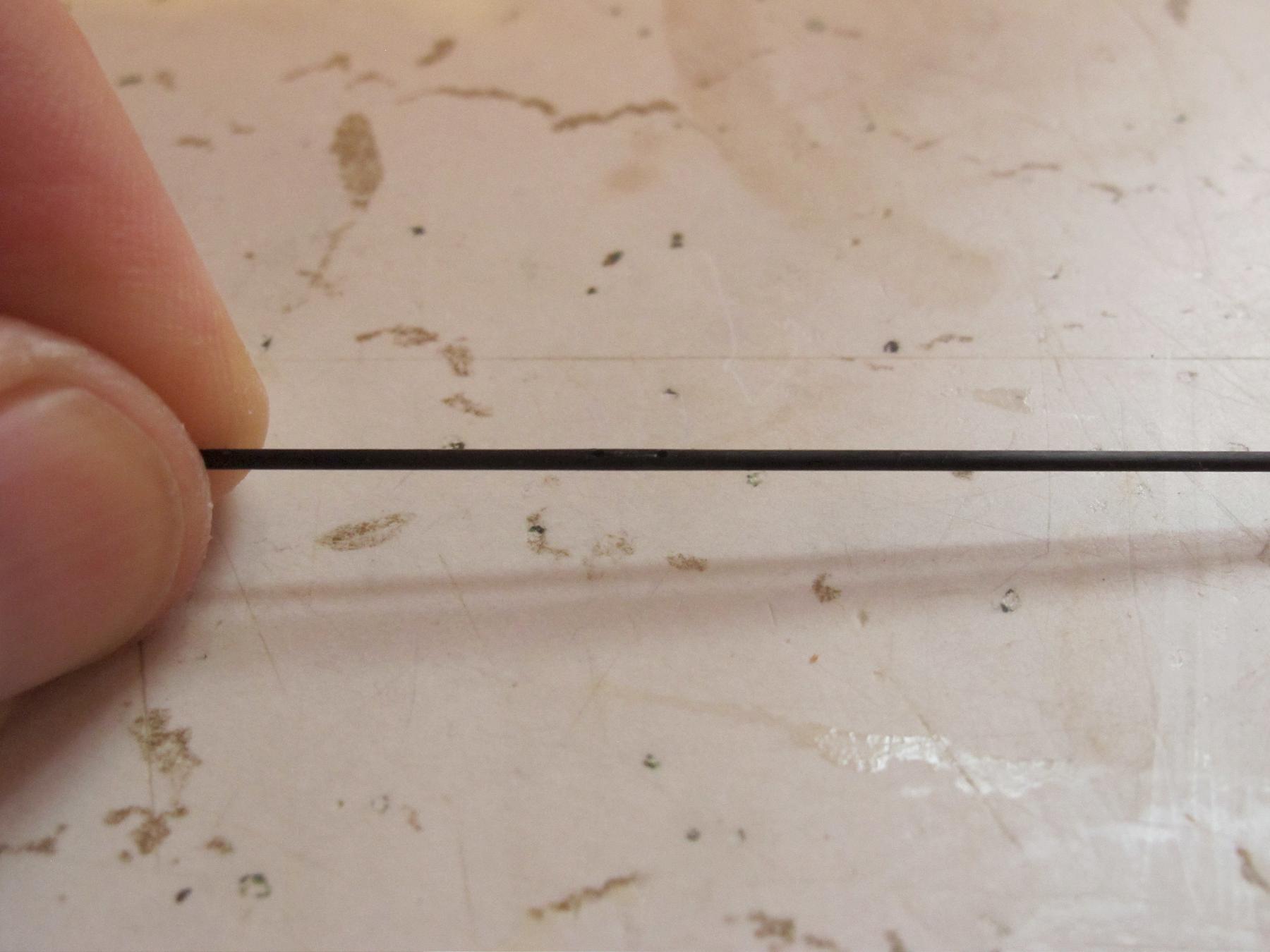
To make the carbon spar, cut a length of 0.039″ carbon tube ~4″ long.
Alternatively you might just want to drill the hole 2″ from the end of the tube before cutting it off. This way if you goof up, you only lose 2″ instead of 4.
A bit of experimentation on length here might be best. At the center, drill a hole through using a #80 drill bit on a drill press. This fits a 0.013″ prop shaft perfectly. Alternatively a #78 or #79 bit should work if you want to use 0.015″ music wire instead.
The best way to drill the hole is to lock the tube tightly into a 0.040″ slot.
You can purchase a router bit this size and feed a bit of wood through a router table (or drill press very slowly) to get the slot cut. Alternatively a bit of 1/16″ ply base with some 1/32″ ply to make a 0.040″ gap would work.
Next I drill another hole about 1/8″ away from the center, drilling just to the center of the tube. You can bend the prop shaft over to go into this hole. A bit of Kevlar thread and glue will bind it together. Just add a Teflon washer and rubber hook to your liking.
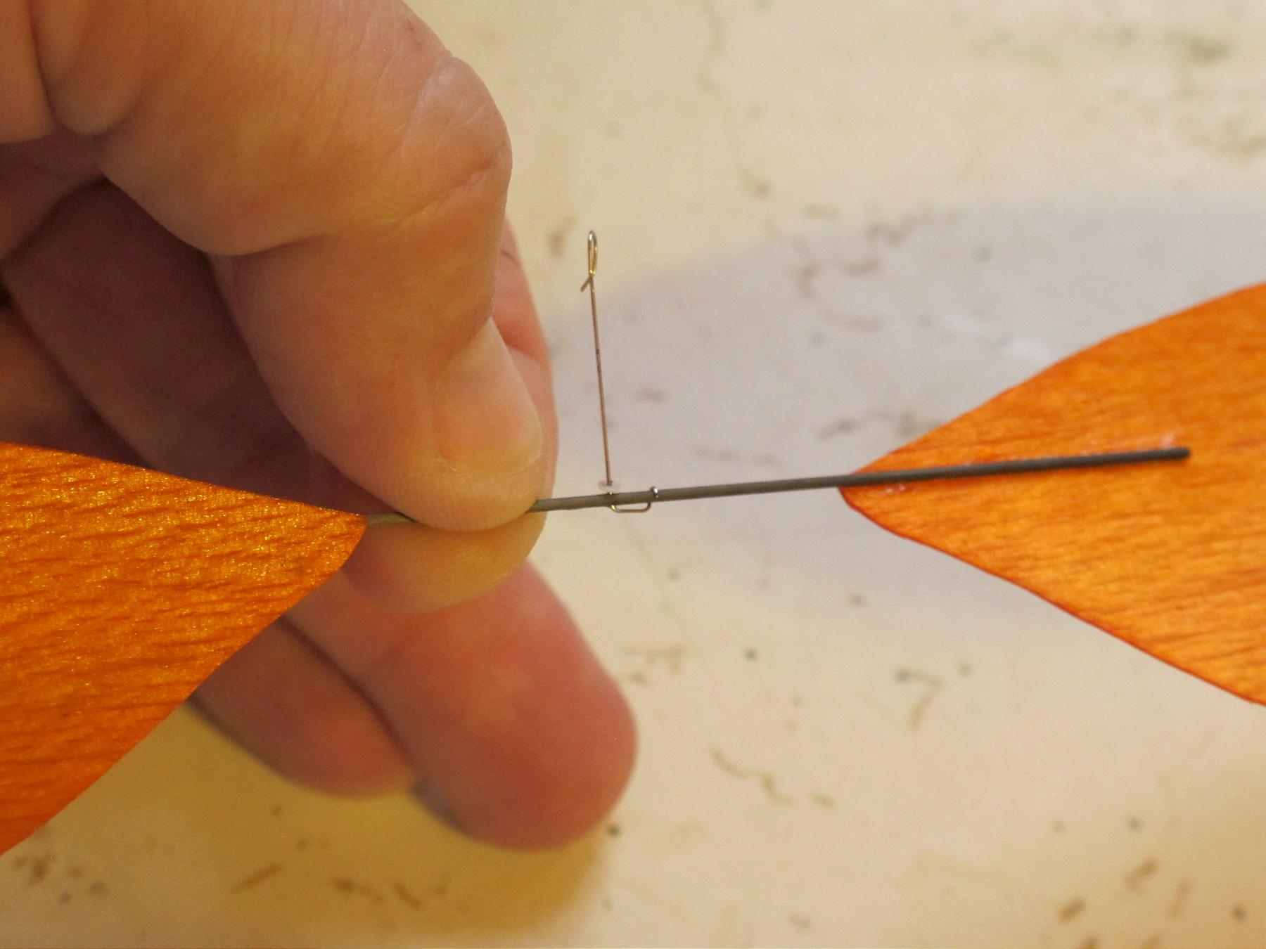
Next put the the spar into your prop pitch fixture. Add glue (Ambroid) directly to the carbon tube, then put the blade on top. Quickly tape the blade in place with blue tape. The spar may also be taped to the underside of the blade. Let dry completely, then check the pitch. Sometimes the glue shrinkage will change the pitch. A bit of acetone to loosen it, twist a bit more in the opposite direction, then let dry. Keep at it until you get it right. Adding plasticizers to the glue may help.
CST or ACP will carry the 0.039″ carbon tube. You may be able to order through a local hobby shop.

Slot for drilling jig
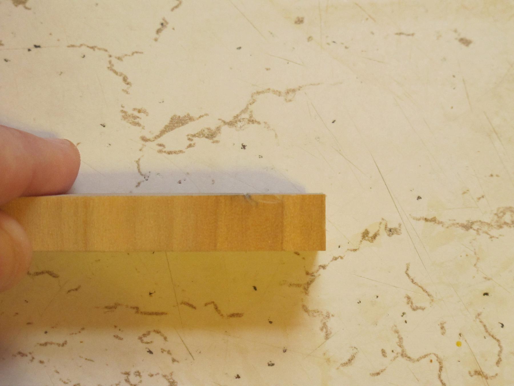
Side view of slot for drilling jig

Tube pushed into place for illustration
Holes from top
Tube turned slightly to show both holes
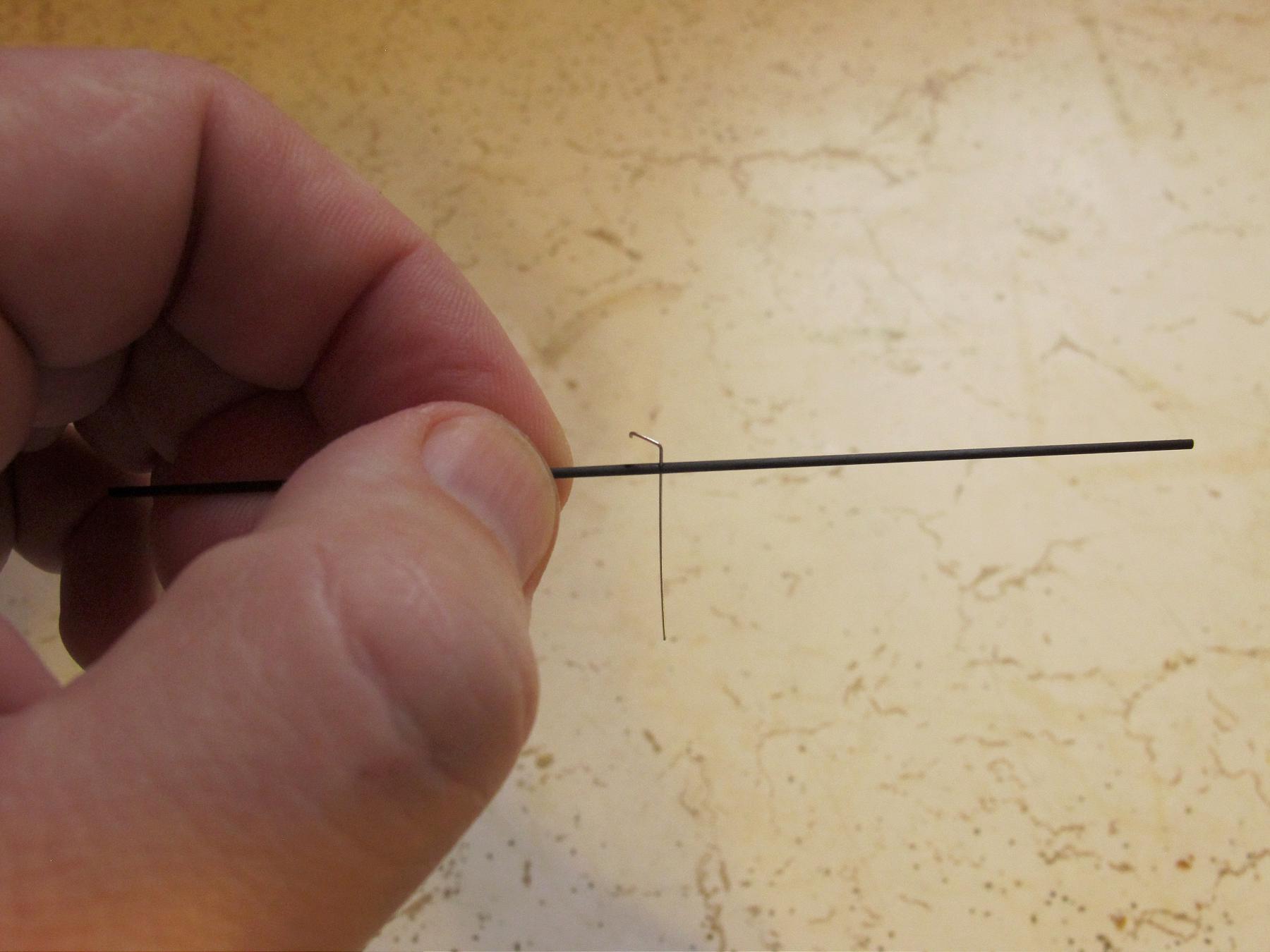
Prop shaft inserted – Not aligned to show hole.
Alternative prop shaft holder does not require second hole

Spar glued onto prop blade
View more by category: Uncategorized (292). .

