
NON-HELICAL PITCH PROP BLOCK IN FUSION 360 by David Campbell
1) https://www.autodesk.com/products/fusion-360/free-trial Download and register as an enthusiast/hobbyist. This makes the license free.
2) Open Fusion 360. Put in Design Mode, File new (From Design), click on origin to show origin and 3Dview planes (Fig 1).
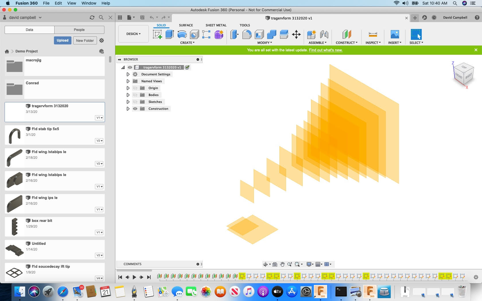
3) Hover your cursor over the 3D gui and click on the house. The view will change to isometric and full screen.
4) To make a 3″ x 10″ Block with Treger Angles at each station along the block I took the angles from the Prop blocks website. You can modify them by using the prop pitch calculator at the link below. http://n-lemma.com/indoorrc/propcalc.htm For this block we will need 14 construction planes along the same axis. (Fig 2)(Chart 1) https://www.youtube.com/watch?v=jmgnFFewwT4

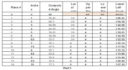
5) Using the plane you select for your first sketch(YZ) click on Construct/Offset plane/enter (-1″) for the distance and click enter. This will create an offset plane 1″ away from the origin plane you clicked first. Repeat for the first 6 inches and then use .5 inches for the rest of the construction planes.
6) Click on the vertical plane of the origin (XZ) Click on Create sketch, draw a line along the center lines of each construction plane as shown in (Fig 3).
7) Click on Construct/Offset Plan/ Create /Create sketch, draw centerline from center point of plane into the upper right quadrant for 1.5 inches at the angle noted on the chart (Chart 1) Plane 1/Inch 1/Local Pitch 26/Upper Right Quad 13.59Deg.
8) Sketch a mirror line from the center point of the plane into the Lower Right Quad at the angle shown in (Chart 1).
9) Mirror the first line using the second line as the mirror line. This will create an equal line (1.5″) into the Lower Left Quad. You could also just sketch the line using the center point of the plane and the angle from the (Chart 1) below for Lower Left Quad. This is the second face showing in (Fig 3). The first is a rectangle at 0 inches. The dimensions of the upper edge is 3″.
10) Sketch a line from each end to a point normal to the bottom of your block. Connect the two lines. If you have sketched each line on the same sketch plane all end points of each line are connected to the connecting lines you should have created a face. It should light up when you click on it. This is your uncambered airfoil shape. If you want a camber add an arc instead of a line.
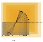
11) Repeat for all planes in chart below. (Chart 1) The drawing should look similar to (Fig 4) . The distance between each line and a smooth arc of the endpoints on each end of the lines.
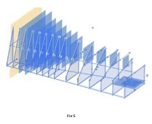
12) Start at one end and slowly click each face, wait until the computer has completed its tasks and click the next face. Continue until each face has been selected then click on OK. When you have all the faces lit as below in (Fig 5), you can loft each section to the next. Again be careful to allow the computer to complete each loft prior to selecting the next face.
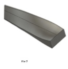
13) You should see a screen like Fig 6. Hide the sketches and construction planes and you should see Fig 7. https://www.youtube.com/watch?v=XkKTXKp-ziI&t=334s I added a radius to the upper edge but its up to you.

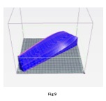
14) Click on File/3DPrint , select the model,and unclick send to 3D Print Utility. Click on OK. You should get a model like the one (Fig 8)(tesselated with triangles)

Save it as an STL file, send to a printing service or print on your personal printer
I got lots of help from John Kagan and others for which I am very grateful. There are many different ways to draw the blocks but this one is I think the easiest to explain.
If there are any questions or concerns post the on Facebook


Leave a comment