Archive for the ‘Uncategorized’ Category

Statuses

How To Make Your Own Aluminum VP Screws

In Uncategorized on October 23, 2013 by nicholasandrewray

How To Make Your Own Aluminum VP Screws

Nick Ray

October 2013

I started making aluminum M1 x 0.2 (1mm in diameter with a pitch of 0.2mm) screws following the 2012 World Championships. I based my screws on Ivan Treger’s plans published in INAV 125. The screws covered in this article match his specifications as exactingly as I can manufacture them. Ivan told me that he had moved away from nylon screws because they are molded rather than cut. Due to the molding process the threads have tiny mold marks that degrade the threads inside the screw holder as the screw is turned. A secondary advantage is that M1 x 0.2 screws have approximately 127 threads per inch. Compared to a 00-90 nylon screw with 90 threads per inch, it is easier to make fine adjustments.  The M1 screws are theoretically slightly heavier than their 00-90 nylon counter parts. However, my milligram scale cannot detect the difference in the finished products. The process of making screws is certainly more time consuming than buying them. Nevertheless, the finished product is more precise and I find a certain charm in making them myself.

Figure 1: The setup

Figure 1: The setup

The smallest diameter machinable aluminum rods I have been able to find to date are from K & S Engineering. They can be found at most local hobby shops in the U.S. and online from various sources.  I buy the 1.6mm/0.0625” rods because next size down are too small at 0.8mm/0.03125”.  There are three ways that I know of to reduce the rod diameter to the 1mm/0.0395”diameter required for threading. The rod can be drawn, turned or my personal favorite, abraded, to appropriate diameter. I do not have a lathe, and my draw plate is imprecise, so I use the abrasion method described below.

I start by cutting about a 38mm/1.5” section from the rod and placing the section into my keyless-chuck Dremel. I then take a piece of 80grit wet/dry sandpaper and dampen it with cutting fluid. (Actual cutting fluid is great but olive oil works fine too) Then I turn the Dremel on low and sand the rod uniformly along its length down to about 1.15mm/0.045”. Next, I switch to an intermediate 320grit wet dry paper and repeat the process until the rod is 1.04mm/0.041” in diameter. I finish abrading the rod with 2000grit wet dry sandpaper. It is very important to check the diameter frequently and rewet the paper frequently. The cutting fluid helps to reduce heat, which changes the properties of the aluminum and it keeps the sandpaper form becoming clogged.
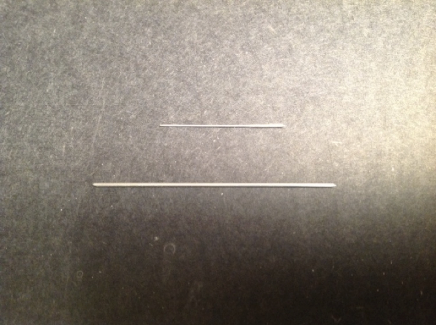
Figure 2: The top piece is a finished rod and the bottom is an oversized piece of original stock

Figure 2: The top piece is a finished rod and the bottom is an oversized piece of original stock

Now that I have the material sized correctly, I cut off an approximately 9.5mm/0.375” long segment and chuck it into a pin vise.

Figure 3: 9.5mm/0.375” x 1mm/0.0395” rod held in pin vise

Figure 3: 9.5mm/0.375” x 1mm/0.0395” rod held in pin vise

It is now time to thread the rod. I bought  a 15 piece tap and die set made by SE from amazon.com. There are several options available, but this seems to be a case where one gets what they pay for. I would discourage anyone from buying the cheapest options available.  The die does not need to be incredibly hard for cutting aluminum threads, but it does need to meet the desired specifications for the screws one wants to make. If the die comes with taps that match the threads it cuts, that is a major plus.

To start, I dip the end of the rod into some cutting fluid and gently turn it clockwise into the die. You should feel rod start to thread. If it does not thread easily check to make sure the rod is sized correctly. My die is not sensitive to burs leftover from cutting the rod to length, though this may be a consideration for some dies. After you have managed about three full rotations, turn the rod counter clockwise to back it out and clean the newly cut threads with cutting fluid. It may help to over lubricate die and wipe off the excess cutting fluid with a rag. Once the threads are clean dip the rod in cutting fluid again resume threading. Keep repeating this process until you have more than enough threads cut to produce a finished screw of your desired length.

Figure 4: An aluminum rod held in a pin vise being threaded into the thread cutting die

Figure 4: An aluminum rod held in a pin vise being threaded into the thread cutting die

Figure 5: View from the bottom/output side of the die.

Figure 5: View from the bottom/output side of the die.

If you fail to clean out and lubricate the die while you are cutting, the rod may breakoff in the die. Depending on where that happens along the rod, there are a variety of not-so-fun options. The easiest is to cut a slot in the rod and back it out with a screwdriver. If that is not an option, you may be forced to drill through the center of rod, careful to ensure that you do not damage the die, and then clean out the remains of the rod with a tap. If all else fails, buy another die.
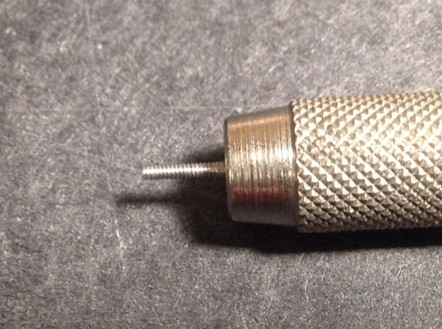
Figure 6: Finished threaded rod held in a pin vise

Figure 6: Finished threaded rod held in a pin vise

To begin the screw head slotting process, finger thread the rod back into the die. If you have something else that is tapped to match your screw you can use that as a screw holder for this part of the process as well.

First, cut off the excess rod about off about 1mm/0.395” above where the threads stop. Then, using a fine metal file, smooth the top of the screw head. One can either leave a little of the unthreaded rod remaining or file the rod down to the threads as Ivan Treger does. If a portion of the unthreaded rod remains, then the screw will stop before it threads too far into the screw holder to be retrieved. The trade off is there is less usable screw per unit weight than there would be if no unthreaded rod were allowed to remain.
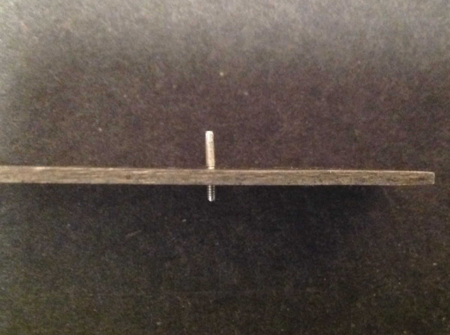
Figure 7: Threaded rod hand threaded into the die for making the screw head
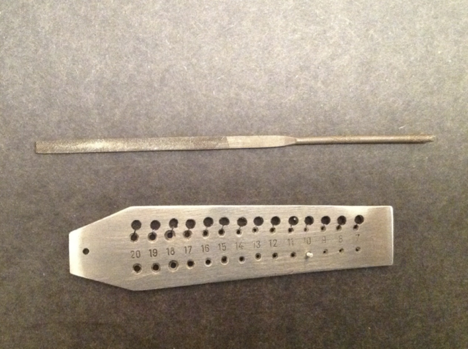
Figure 7: Threaded rod hand threaded into the die for making the screw head

Figure 8: Threaded rod with the top of rod filed smooth

Figure 8: Threaded rod with the top of rod filed smooth

After what will become the head of the screw has been filed satisfactorily smooth, visually divide the top of rod into two equal parts. Use a single edge razor blade to score the top of the rod in the middle. This score mark will guide the saw when starting to cut the slot in the head of the screw.  If your score mark is not perfectly centered then polish it away and try again. I make the heads of my screws first so that I do not have to worry as much about my screw coming out too short if it takes more than one try to get this step correct.

Figure 9: Scored screw head

Figure 9: Scored screw head

Next use a fine Zona or jewelers with about a 0.2mm/0.008” kerf to cut a grove 0.5mm/0.02” deep into the head of the screw. Lastly polish off any burs remaining on the head of the screw with a fine metal cutting file.

Figure 10: Head slotting saw

Figure 10: Head slotting saw

Figure 11: Finished screw head

Figure 11: Finished screw head

The screw now needs to be filed to the appropriate length. The finished length of your screw will depend on the design of your hub. The rule of thumb that I like to use is when your low and high pitch screws are turned completely in, they should stop the prop from changing pitch. The spring screw should be long enough that when it is turned completely in, the spring should be at its maximum range of travel.  If you are following Ivan Treger’s plans this will mean that your high and low pitch stop screws will be 2.3mm/0.091” long and your spring screw will be 3.5mm/0.138” long.

I use a fine metal file to size the screw to the desired length. It is critical that the finished screw bottom be perfectly flat. If it is not, adjustments will be inconsistent as the screw is turned. It may help to visually line the file up parallel to the die. Turn the screw periodically to make sure that while the screw is flat when looking at from one direction, it does not become uneven from another.

If you are making a low or high pitch stop screw, you are now done. However, if you are making a spring screw there are still a few steps remaining.

Figure 12: The bottom of the screw after filing it down to the appropriate length

Figure 12: The bottom of the screw after filing it down to the appropriate length

To being making a hole for the terminal end of the spring, first locate the center of the screw and use a pin to score the center so that the drill bit does not wander. Then use a 0.4mm/0.0157” drill bit to make a hole 1mm/0.0395” deep into the center of the screw. I have found it helpful to place a drop of cutting fluid on the tip of the drill bit once I get the hole started, to reduce friction and to keep the screw from backing out of the die. Take care to keep the drill centered so as not to destroy the screw or the die. Finish the screw by gently polishing off any burs on the bottom of the screw with a fine metal file.

Figure 13: Bottom of spring screw and scoring pin
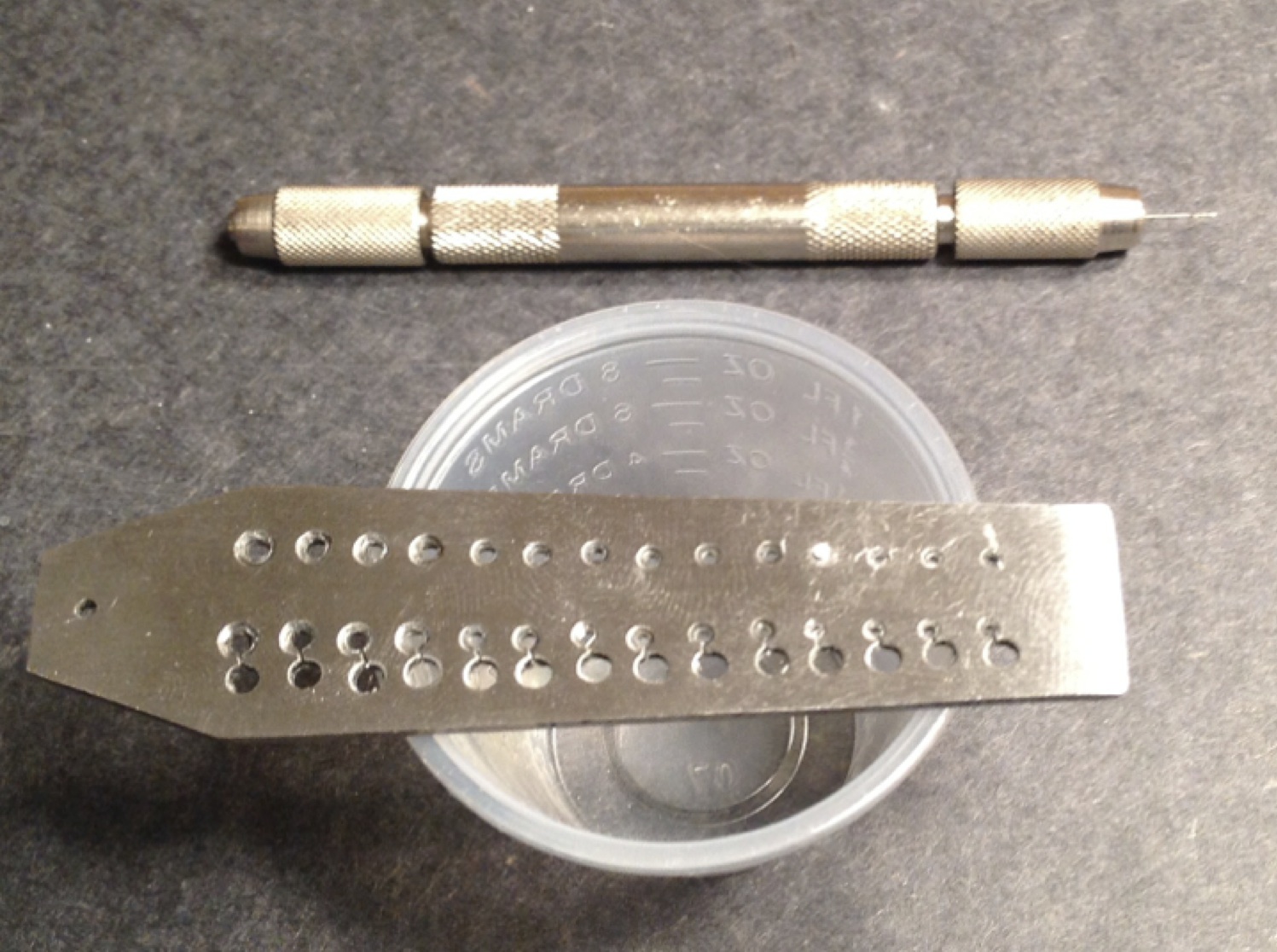
Figure 13: Bottom of spring screw and scoring pin

Figure 14: Pin vise with 0.4mm/0.0157” drill bit

Figure 14: Pin vise with 0.4mm/0.0157” drill bit

Figure 15: Finished spring screw viewed from the bottom
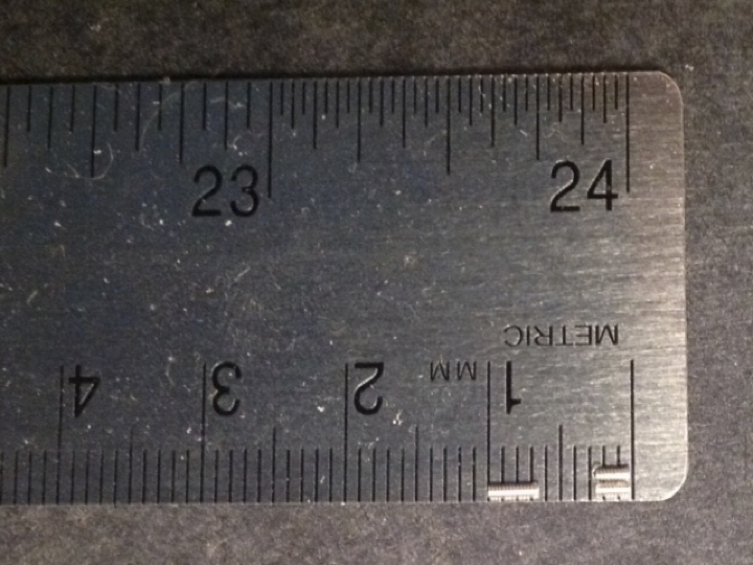
Figure 15: Finished spring screw viewed from the bottom

Figure 16: Finished screws: spring screw on the left and low and high pitch stop screws on the right

Figure 16: Finished screws: spring screw on the left and low and high pitch stop screws on the right
 

Statuses

Yuan Kang Lee’s F1D

In Uncategorized on September 26, 2013 by nicholasandrewray


Yuan Kang Lee’s F1DKang 2013 F1D FinalClick here to download a PDF of Kang’s plan.

Statuses

A New US Indoor Balsa Wood Supplier

In Uncategorized on September 17, 2013 by propblocks

Update:

Phedon has decided to stop cutting Indoor wood as of mid-2014.

Original Post:

A new wood cutter has appeared in the US – Phedon Tsiknopoulos out of California.

There are one or two guys cutting their own wood in the US but not selling. Jeff Hood seems to have closed Hood’s Wood for now. A2Z seemed to be the sole US commercial supplier, but my last couple of orders underwhelmed- I started ordering from Nick Aikman (Greenman Balsa) and never looked back.

I always worry what would happen if Nick Aikman stopped cutting wood.

So when a post appeared on the Yahoo Indoor Construction group announcing Phedon was supplying ground Indoor balsa wood, I wanted to check his wood out.

I started to build a new wing for my F1D for USIC and realized that somehow I had left off the wood I wanted for wing spars from my last order with Nick. So I decided to try Phedon. I also ordered some tapers as Nick doesn’t cut them.

I placed an order and waited. USIC came and went – I was no longer in a hurry. We converse occasionally via e-mail. I get another email asking me to reconfirm my order. Approximately six weeks after initiating contact he tells me the final price and that the order is ready.

Phedon requests a check for payment. I send it. He sends me the balsa on a Thursday and I receive it on the next Monday.

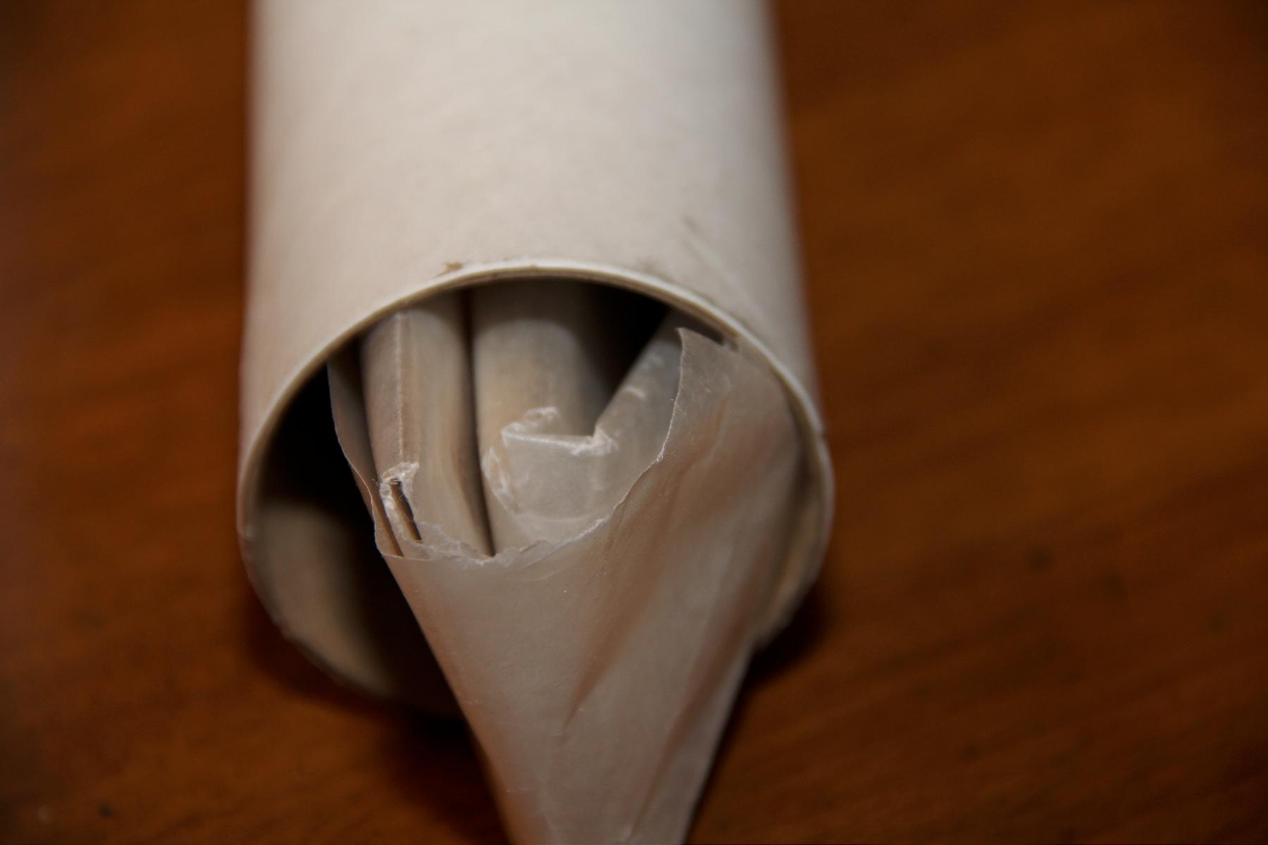
The packaging states clearly ‘Open Here’. Two bits of tape hold the end cap in the paper tube. I shake it a bit and hear the balsa moving around. I opened it up and find the balsa separated – Four sheets of wing spar wood wrapped together and the tapers wrapped separately in what appears to be wax paper.

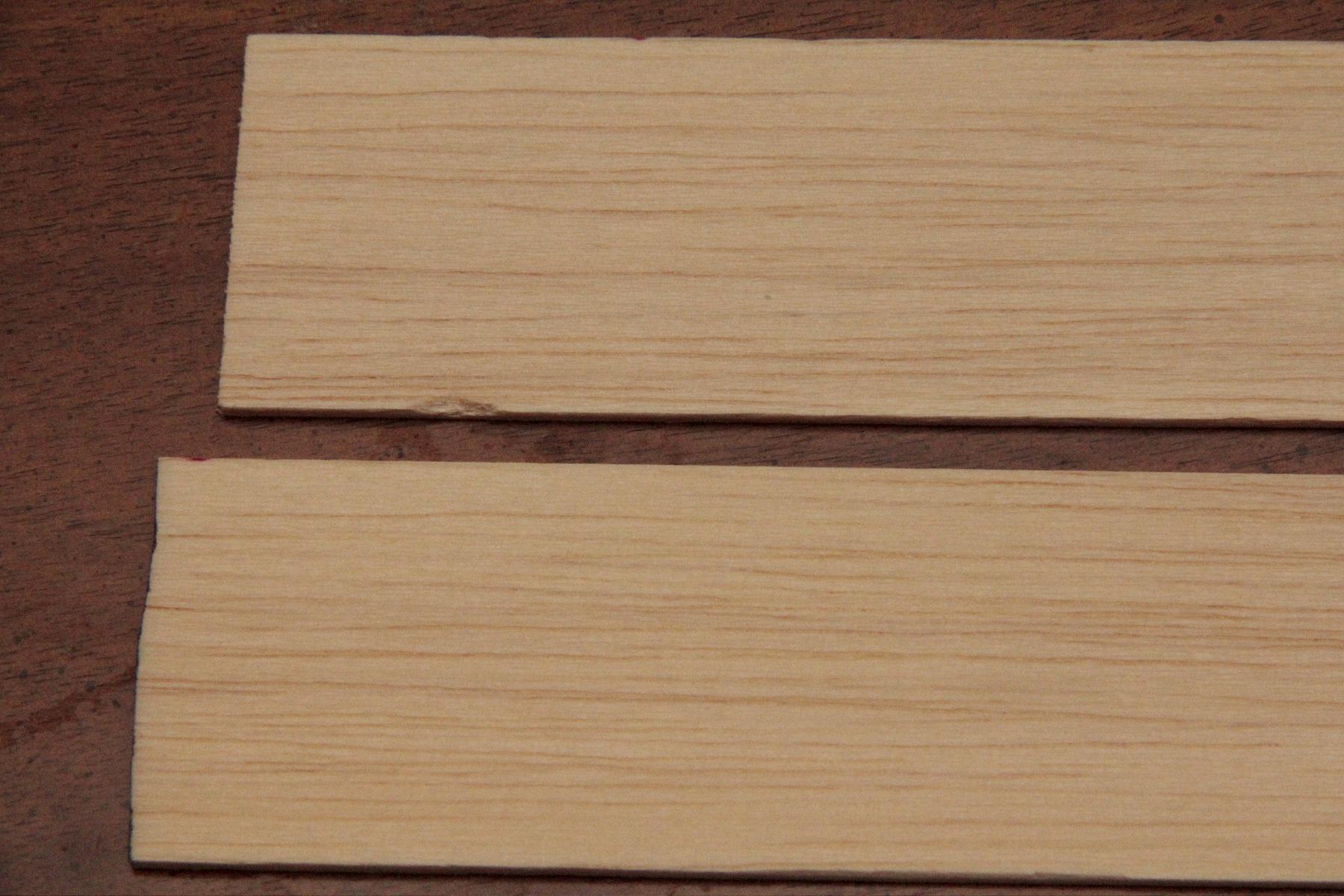
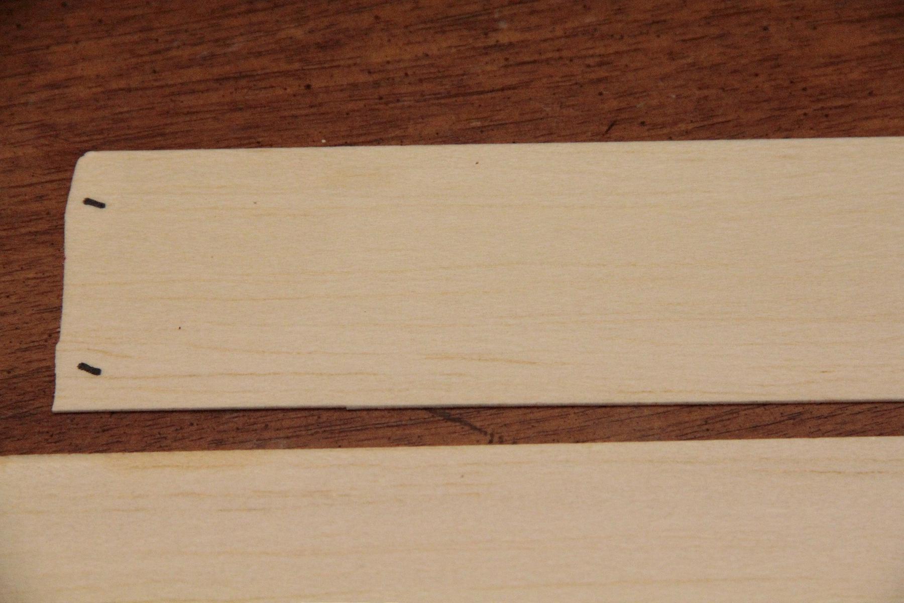
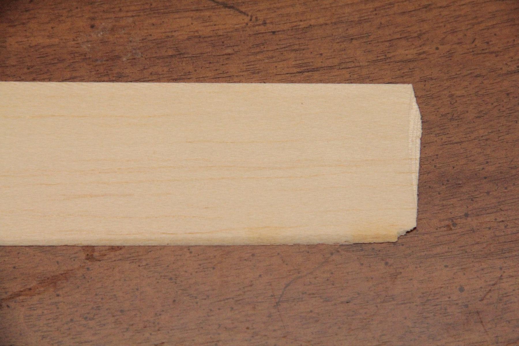
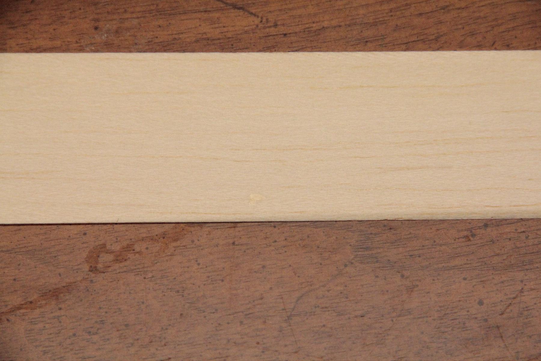
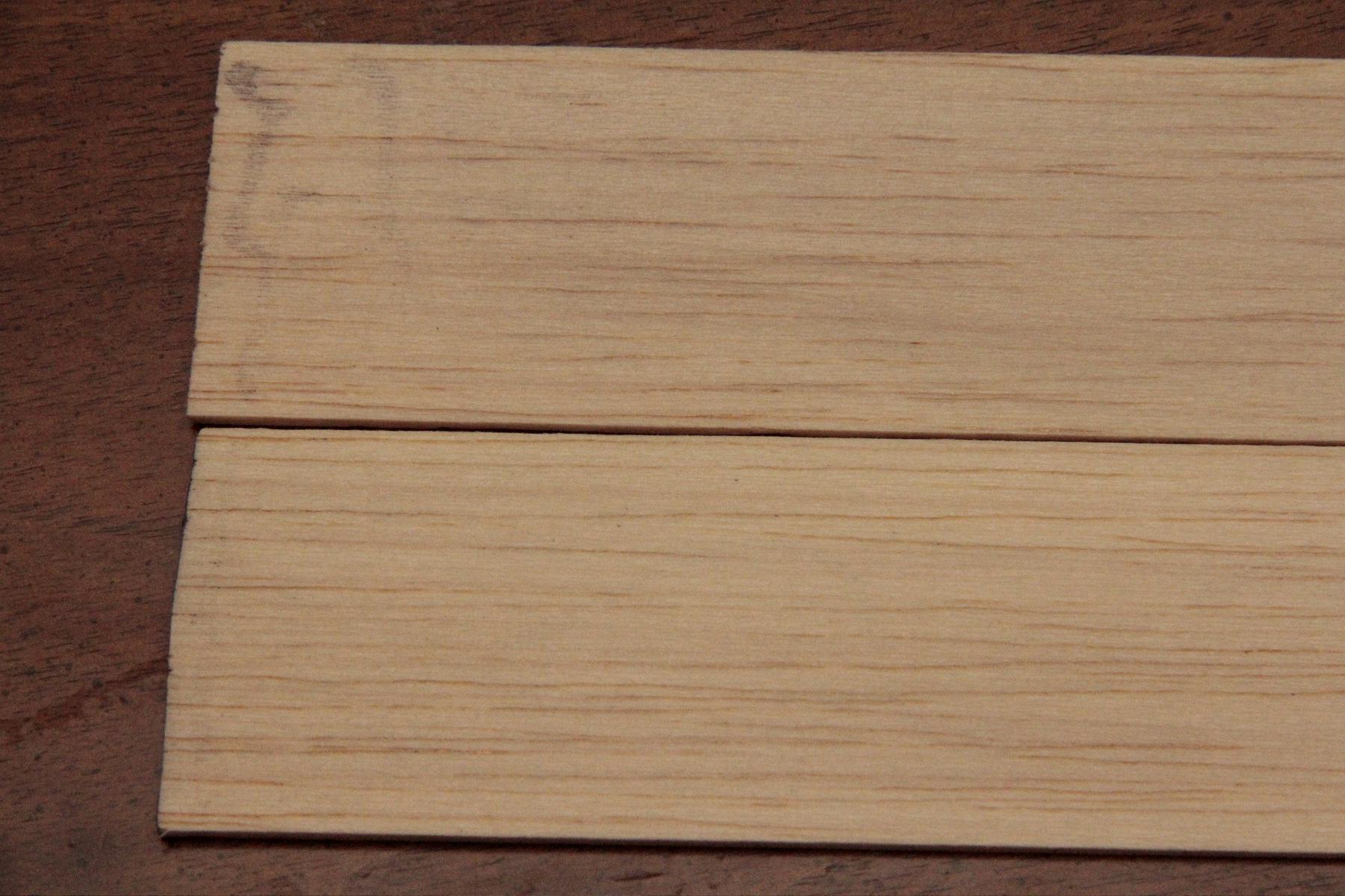
When I open the wood itself, it is about what I expected. The edges are not dressed – The wood was cut at an angle and the angle appears on the edge of the wood. The wood is not labeled with weight or thickness. The surface of the wood appears to be extremely smooth. The wood is within 0.001″ of what I ordered, of very consistent thickness, and in the density range specified.

So how does it compare to Greenman Balsa?

Pros: He cuts tapers to order and they are within 0.002″ of what I ordered. The thin ends vary slightly, but this I can live with.
We have another US supplier.
Wood supplied is within the density range I specified.

Cons: Shipping is not up to the standard set by Nick Aikman. Nick uses thicker tubes, ends are quite securely taped and the wood is sandwiched between thicker balsa, taped carefully together and usually wrapped in bubble-wrap or packed with balsa triangles.
Nick takes PayPal versus check.
Phedon’s prices are higher, although offset somewhat by ‘free’ shipping/insurance.
Shipping took longer than I would have liked.
Two of the tapers have an odd grain to them.

Phedon's wood tapers

Phedon’s wood – Two of the tapers have an odd grain pattern. Time will tell if these are suitable for prop spars.

Phedon's wood - Two of the clean tapers have this odd drawing maybe on the back.

Phedon’s wood – Two of the clean tapers have this odd drawing maybe on the back.

Phedon's wood - Top side of two of Phedon's tapers

Phedon’s wood – Top side of two of Phedon’s tapers

Phedon's wood

Phedon’s wood

Phedon's wood

Phedon’s wood

Example of non-dressed edge on Phedon's wood

Example of non-dressed edge on Phedon’s wood

Phedon's wood - note angle on lower front right edge and odd discoloration in middle.

Phedon’s wood – note angle on lower front right edge and odd discoloration in middle.

Phedon's wood

Phedon’s wood

Phedon's wood - Another example of non-dressed edge.

Phedon’s wood – Another example of non-dressed edge.

Packaged in wax paper, loose in thin-walled shipping tube.

Packaged in wax paper, loose in thin-walled shipping tube.

No need to guess where to start.

No need to guess where to start.

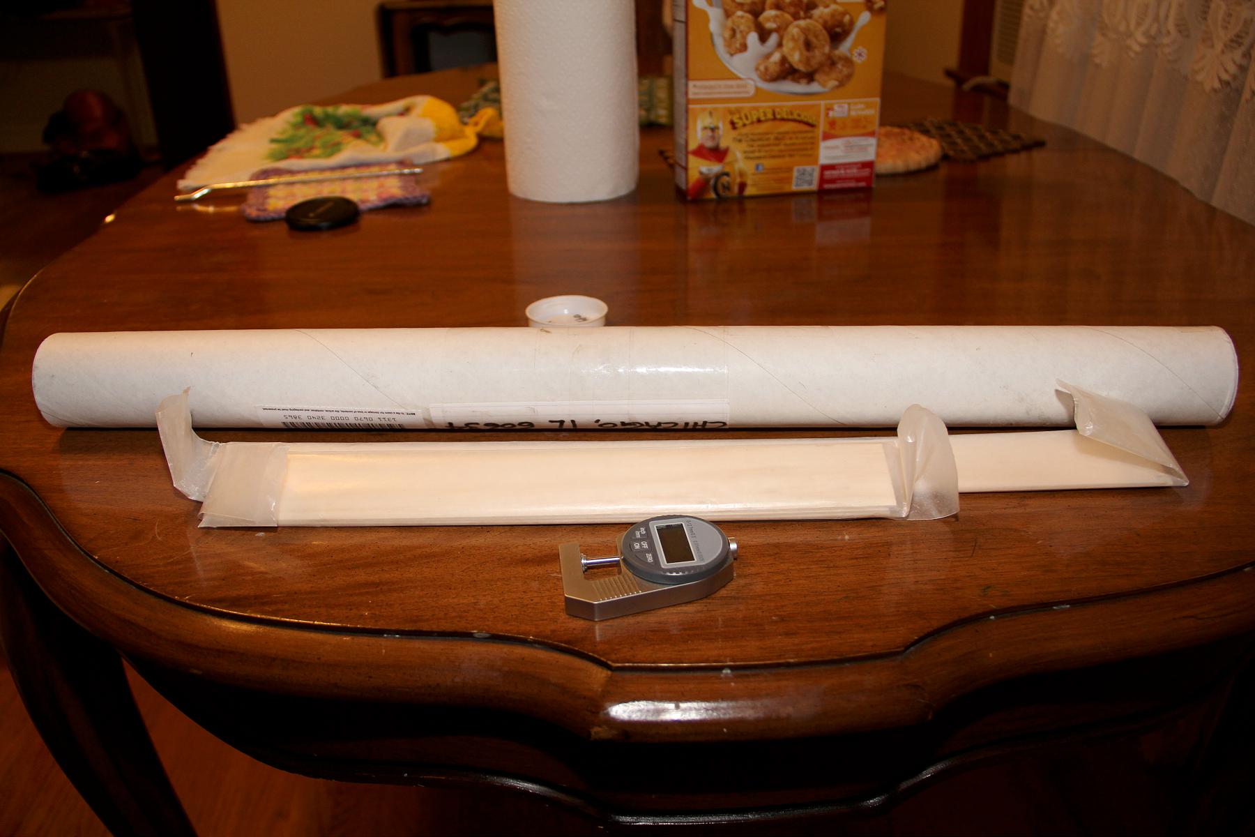
Laid out on the table - Micrometer ready for testing.

Laid out on the table – Micrometer ready for testing.

Now for some pics of balsa from Greenman Balsa as a comparison.

Sheets from Greenman Balsa as a comparison

Sheets from Greenman Balsa as a comparison

Sheets from Greenman Balsa as a comparison

Sheets from Greenman Balsa as a comparison

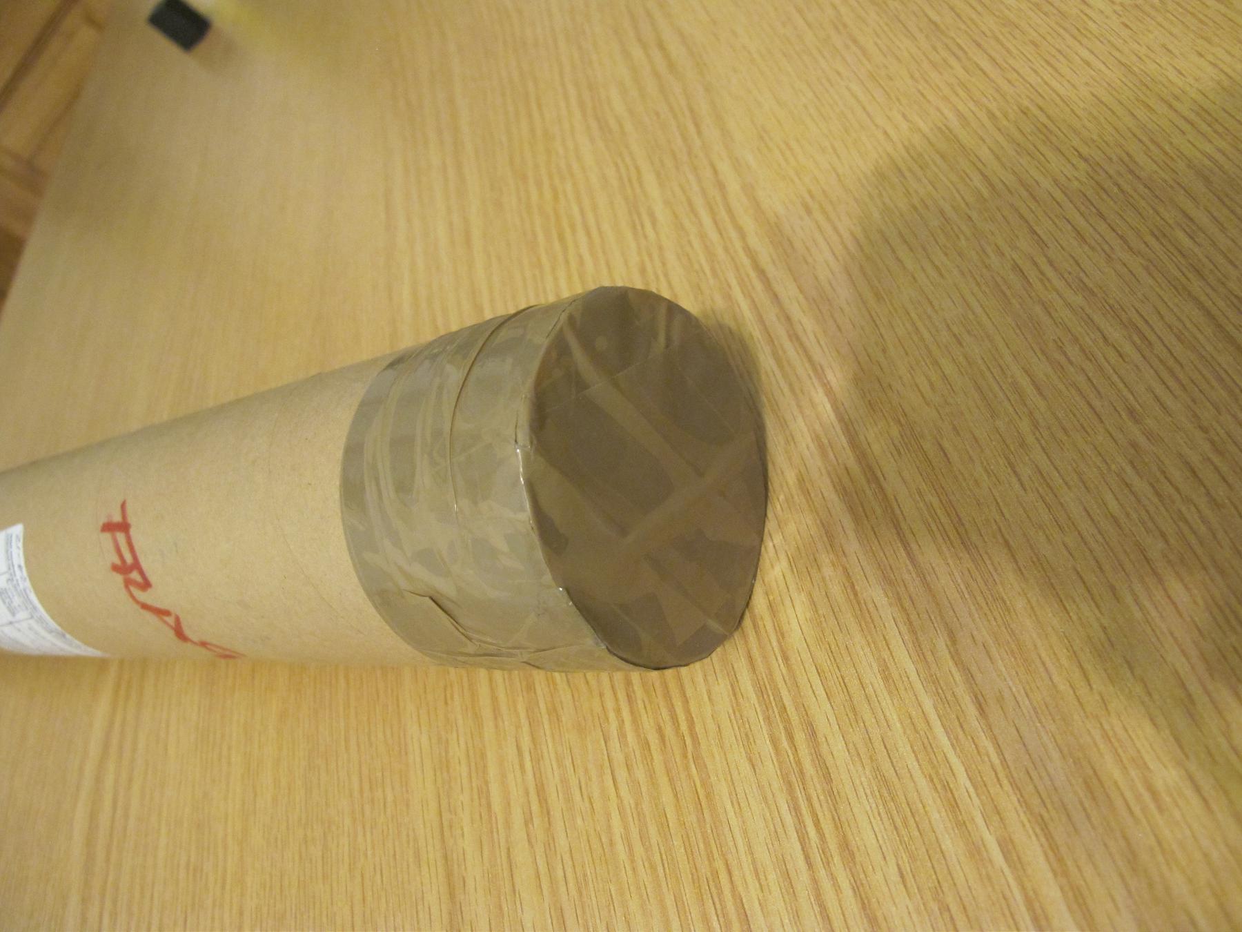
Shipping tube from Greenman Balsa as a comparison

Shipping tube from Greenman Balsa as a comparison

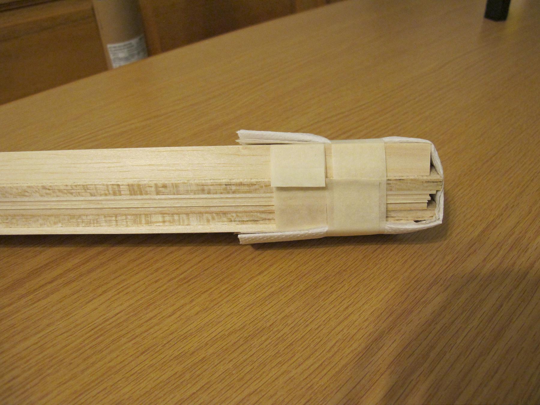
After removing from the tube, Greenman balsa sheets packaging.

After removing from the tube, Greenman balsa sheets packaging.

This detail impressed me - Tape folded over in a tab to easily remove the shipping balsa tapers. Every tape strip is like this. Nick Aikman's attention to detail is quite impressive.

This detail impressed me – Tape folded over in a tab to easily remove the shipping balsa tapers. Every tape strip is like this. Nick Aikman’s attention to detail is quite impressive.

My wife and I have a sort of ritual in new restaurants: We ask ourselves “Would we go here again?”

I am pretty happy with what I received. Phedon may not replace Greenman as my go-to guy for balsa, but I now have a source of tapers I am happier with.

To answer the question, yes, I would order from Phedon again.

Phedon Tsiknopoulos [phedon21t@yahoo.com] is his contact info.

Regards.
Mike Kirda

Statuses

Editor’s Update

In Uncategorized on September 6, 2013 by nicholasandrewray

Editor’s Update

Dear INAV Readers,

I am pleased to announce that we now have a complete digital archive of all the content INAV has published in its 53 years. It has taken me longer than anticipated to scan the issues published by Abram Van Dover. However, they are now all available on the Downloads page.  I want to thank Mike Kirda for helping me make the PDFs searchable.

Regards,

Nick Ray

Statuses

Covering Developments by Lutz Schramm

In Uncategorized on August 29, 2013 by nicholasandrewray

Covering Developments by Lutz Schramm

Some time ago, Current F1D World Champion Lutz Schramm kindly sent me some images of his latest covering methods, and seeing pictures of Nick Ray’s elliptical dihedral F1D prompted me to put this series together for INAV. I hope all is self-explanatory as I have not discussed the fine details with Lutz.

Lutz has used elliptical dihedral on F1D models for some years and he originally applied the covering film with a curved frame. More recently, in pursuit of perfect wrinkle free results, he has developed a system using a purpose built vacuum box.

Figure 1. The jig used to build the dry wing structure. The top surface is made from a sheet of thin flexible plywood.

Figure 1. The jig used to build the dry wing structure. The top surface is made from a sheet of thin flexible plywood.

I assume that the curved spars, tips and ribs are built separately beforehand and this jig is used only for final assembly. Ribs and main spars typically have boron top and bottom. Note that the wing above has six ribs while that in the sequence below has seven.

Figure 2. The vacuum box used to cover the completed wing frame is shown below. The completed dry structure is presumably tacked to the balsa carrier, which locates into slots on either side of the jig for exact positioning. The hole in the side of the box is to accept the clear plastic tube seen in figure 4 and the top of the box is covered with soft thin porous fabric.

Figure 2. The vacuum box used to cover the completed wing frame is shown below. The completed dry structure is presumably tacked to the balsa carrier, which locates into slots on either side of the jig for exact positioning. The hole in the side of the box is to accept the clear plastic tube seen in figure 4 and the top of the box is covered with soft thin porous fabric.

Schramm.3

Figure 3. The wing frame is removed and a sheet of well-crinkled film is then brushed out over the top surface of the jig. This film appears to be Y2K.

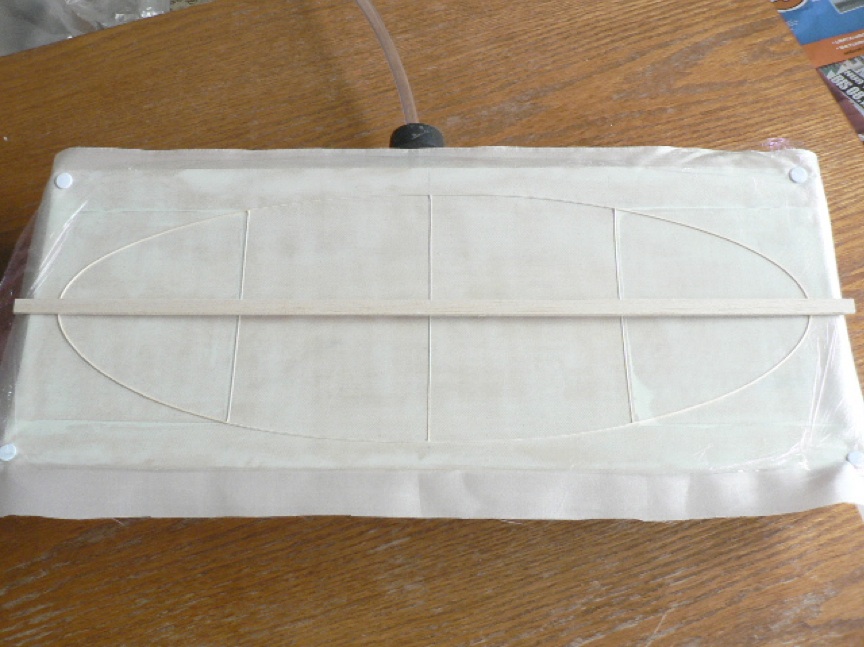
In the image below, the clear plastic tube can be seen on the far side of the box, leading to whatever provides the suction.

Figure 4. In the image above, the clear plastic tube can be seen on the far side of the box, leading to whatever provides the suction.

Figure 5. The wing frame is then reintroduced on top of the film.

Figure 5. The wing frame is then reintroduced on top of the film.

Figure 6. Presumably, the adhesive to glue the film to the structure has already been applied.

Figure 6. Presumably, the adhesive to glue the film to the structure has already been applied.

Figures 7.

Figure 7.

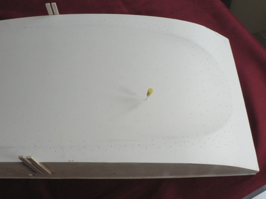
Figure 8. The two images above show the underlying top surface of the box, carved as an exact match to the compound curvature of the wing. A matrix of small holes allows suction to pull the covering film down and hold it in place.

Figure 8. The two images above show the underlying top surface of the box, carved as an exact match to the compound curvature of the wing. A matrix of small holes allows suction to pull the covering film down and hold it in place.

Figure 9. Excess film is removed in the normal way.

Figure 9. Excess film is removed in the normal way.

Figure 10. Lutz also uses this system to cover tailplanes.

Figure 10. Lutz also uses this system to cover tailplanes.

Nick Aikman. 25.08.2013.

Statuses

Indoor Flying at Maker Faires

In Uncategorized on August 27, 2013 by nicholasandrewray

Indoor Flying at Maker Faires

In the Atrium

In the Atrium

Have you ever been to a ‘Maker Faire’? Maker Faires are science-oriented hobby fairs organised to promote science activities. Often they have a strong focus on electronics including robotics, 3D printers, laser cutters and the like.

I knew nothing about them until early this year I heard about one being put together here in Adelaide, South Australia. This is the story of how a model was designed for the event and ended up in front of a crowd of 20,000 a few months later.

Encouraged by flying buddy Dave Putterill, I met with the organisers of the Maker Faire to see if they’d be interested in having some indoor model planes on display. I showed them a few models including an F1D and a Mini Stick. The show was going to be indoors in a large atrium – but would also be (hopefully) full of people.

‘Was it possible to have a model flying over the crowd from time to time?’ they asked.

Well, I was thinking more of a static display or a talk, but I agreed to give it a go. As an afterthought, the organisers said: ‘Is it possible to do a hands-on activity – or a kit people can buy and take away with them?’  Hmmm – ok – I’ll give it a go.

So over a few days I contemplated the age-old aeromodelling problem of what to offer as an ‘introductory model’ for beginners. On top of that – it needed to be something that could be demonstrated within the space available. The Hanger Rat was going to be too big for the space. The Delta Dart is easy to build, but I couldn’t see it as easy to demonstrate as a lighter, slower model. Maybe something like a Mini Stick? Not a ‘beginners model’ but something people with interest and hobby skills could take on as a challenge. After all, a 1/72 plastic models and electronic robotics kits are not easy or aimed at beginners.

Then came another question from the Maker Faire people: ‘What is your exhibit called? It has to be something descriptive like The Dalek Builders Union who will also be there.’

Now here is something I understood. I have a marketing background, so I knew it needed to DO what it said. Five seconds later I came up with ‘The Fly’.

It was going to be covered in tissue (rather than trying to get beginners to use OS Film) and be made a lot easier to handle (which meant heavier). So I made the wing area bigger than a competition Mini Stick.

OK, so now I want to back track a little. We all have a story from our aeromodelling youth. After building a few models with my Dad, one day (1976) I walked into a newsagent and saw a microfilm model on the cover of Airborne Magazine. I was fascinated. My parents lived in a classic 70’s home with a high pitched roof with exposed beams. So I started building tissue-covered stick models small enough to fly around the living room. Short span, lots of wing area and steep dihedral tips at the end of a flat rectangle wing. Forty years later I’d finally found a use for all this practice!

With this experience in mind, The Fly prototypes took no time to put together. I like the modern look of the vertical tip fins on wings and stab that have taken over in Mini Stick and Penny Plane classes in recent years. They are easier to cover than wings with dihedral joins. The wing makes a nice ‘canvas’ for whatever you want to draw or print on the surface. The size makes it easy to fly in a small area. Even though some exhibition space are big – it is difficult to track and recover a big aeroplane with a wide turning circle. The Fly was designed to stay close and buzz around your head like…  well, like a fly…

Armed with 20 kits, a few prototype demo models, and a few posters, I went along to the Maker Faire and had a great time just flying all day and talking about indoor flying to science and crafts oriented people. I didn’t break or lose a single model. Sold all 20 kits by noon.

Encouraged by the success, a few of the Ingle Farm indoor free flighters embarked on another event – a Hobby and Craft Fair. My hats off particularly to Dave, Max and Jack who spent many hours with me that weekend. Lots of interest… but maybe not the right crowd mix. More Art & Crafts than Science.

Most recently – and the biggest of these events – was called Science Alive! This was a science expo organised as part of National Science Week.

About 20,000 people attended over 3 days. The expo included careers information stands for universities and science research organisations. I did a lot of demos and showed people how to wind and fly – let people have a go etc…   Good fun but quite exhausting!

We were next to a giant smoke generator which added to the crowd interest (www.youtube.com/watch?v=P8X8w6ESPvs) and there has been some significant interest from schools and other organisations.

I’ve tried a number of different strategies in connection with the project including:

  • handing out free copies of the plan and instructions to interested attendees
  • making the plan a free download from various sites including my own (maker communities use the ‘open source’ concept as a popular way of engaging and encouraging interest)
  • offering a free-to-enter raffle prize in exchange for attendee email addresses (with proviso that you will receive at least one newsletter – at which time you can then opt out if not interested).

For those who have tried something similar, you’ll know that it is hard work. But the benefits are certainly there. For example:

  • making contacts with indoor venue owners
  • talking to school teachers about possible projects
  • showcasing and promoting an activity that is seldom seen.

The gentleman with the smoke generator (Mark Thomson) is also the author of two great publications: ‘Blokes and Sheds’ and ‘Rare Trades’.

He said the real reward for most of us, is just that moment in someone’s eyes – that look of disbelief, inspiration or innocent wonder – at seeing something they never knew existed. That’s probably enough.

However, going back to the magazine I saw in my teen years – an early introduction, planting the seed, may have a long term effect that we will never know about.

Example: The magazine I saw in 1976 described Boyd Felstead’s Australian national record flight made that year at Centennial Hall. His time was 26:42 – and it stood for many years. The Science Week event I attended was at a new Expo building, on the same site as Centennial Hall (which is no longer). So for me it’s hallowed ground. In fact, I was given a piece of Aero-Lite balsa handed down from the days when Boyd Felstead, Gordon Burford, Max Starick, Mal Sharpe, Stan Grey and others flew at this venue. As a sentimental bloke, I used a bit of this wood as boom joiners in my Belgrade models. When I looked back at the data, my best time at Belgrade (in the Dorcol) was exactly the same as Boyd’s – 26:42. A nice bit of symmetry.

Now days, of course, there’s more you can do to support an event like a flying model display. It’s more work, but providing information online, as well as ‘being there’ in terms of social media is of increasing importance. So I tried to do all that too, including youtube, twitter etc. So some links are provided below as examples.

The Fly has a facebook page  (if you are on that) with more photos: http://www.facebook.com/pages/The-Fly/177946499051233

And I managed to get a web page up in time for the event which is at: www.theflyadelaide.wordpress.com  that way if people downloaded the plan they had a local contact to get supplies or a kit.

I hope this was an interesting tale both for those who have already tried something like this, or who want to give it a go. Good luck!

Cheers

Tim Hayward-Brown

Tim with The Fly

Tim with The Fly

Fly Display

Fly Display


Stand

Stand


Statuses

Larry Coslick’s Unbraced Intermediate Stick

In Uncategorized on August 23, 2013 by nicholasandrewray

Larry Coslick’s Unbraced Intermediate Stick 

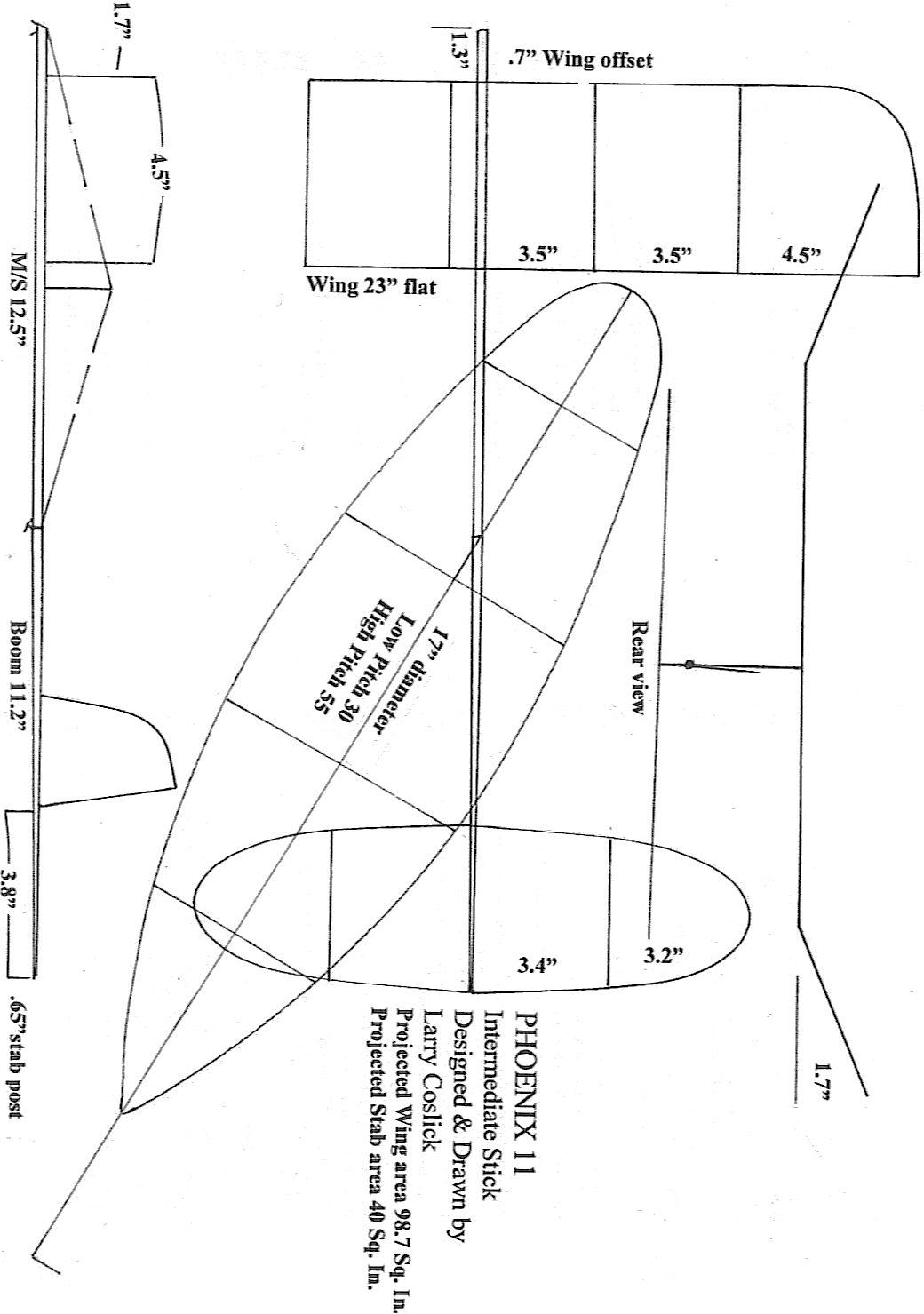
Int stk 3 view unbraced

Int. stick wood densities, unbraced. 2006

Click here to download a copy of the Larry’s plan.

Statuses

2013 Kibbie Dome Report by Tony Hebb

In Uncategorized on August 23, 2013 by nicholasandrewray


2013 Kibbie Dome Report by Tony Hebb

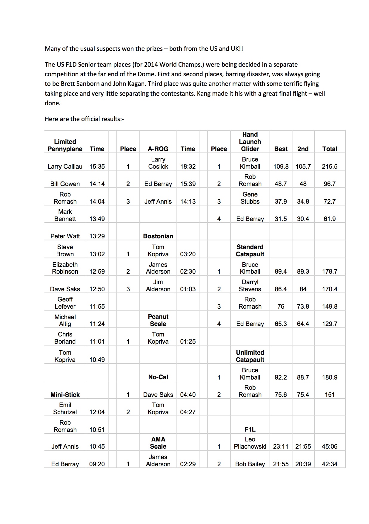
This article previously appeared on http://indoorduration-gbr.co.uk Tony has generously allowed INAV to republish it. 
Hebb.1
Hebb.2 Hebb.3 Hebb.4 Hebb.5 Hebb.6

Statuses

2013 F1D European Championships

In Uncategorized on August 19, 2013 by nicholasandrewray

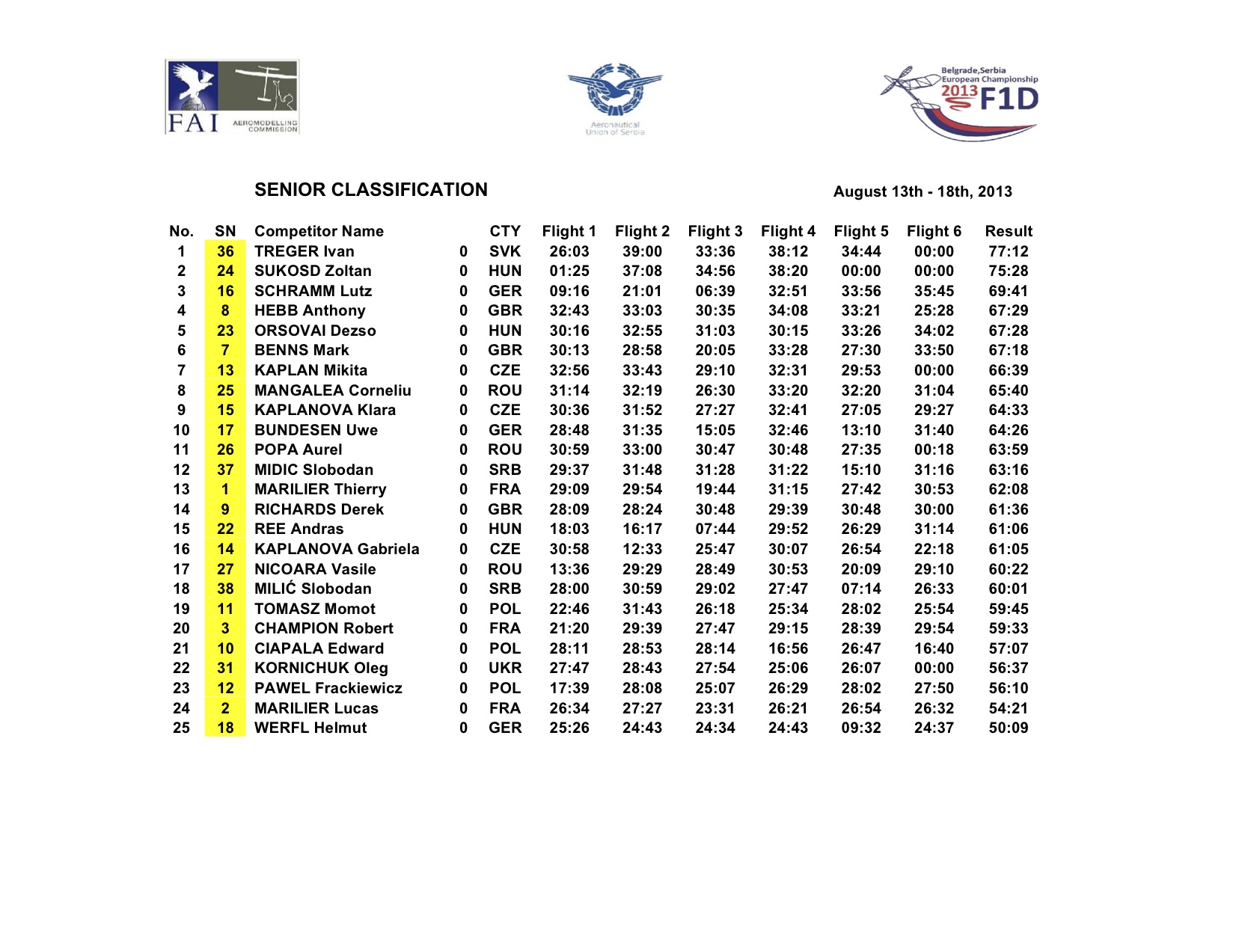
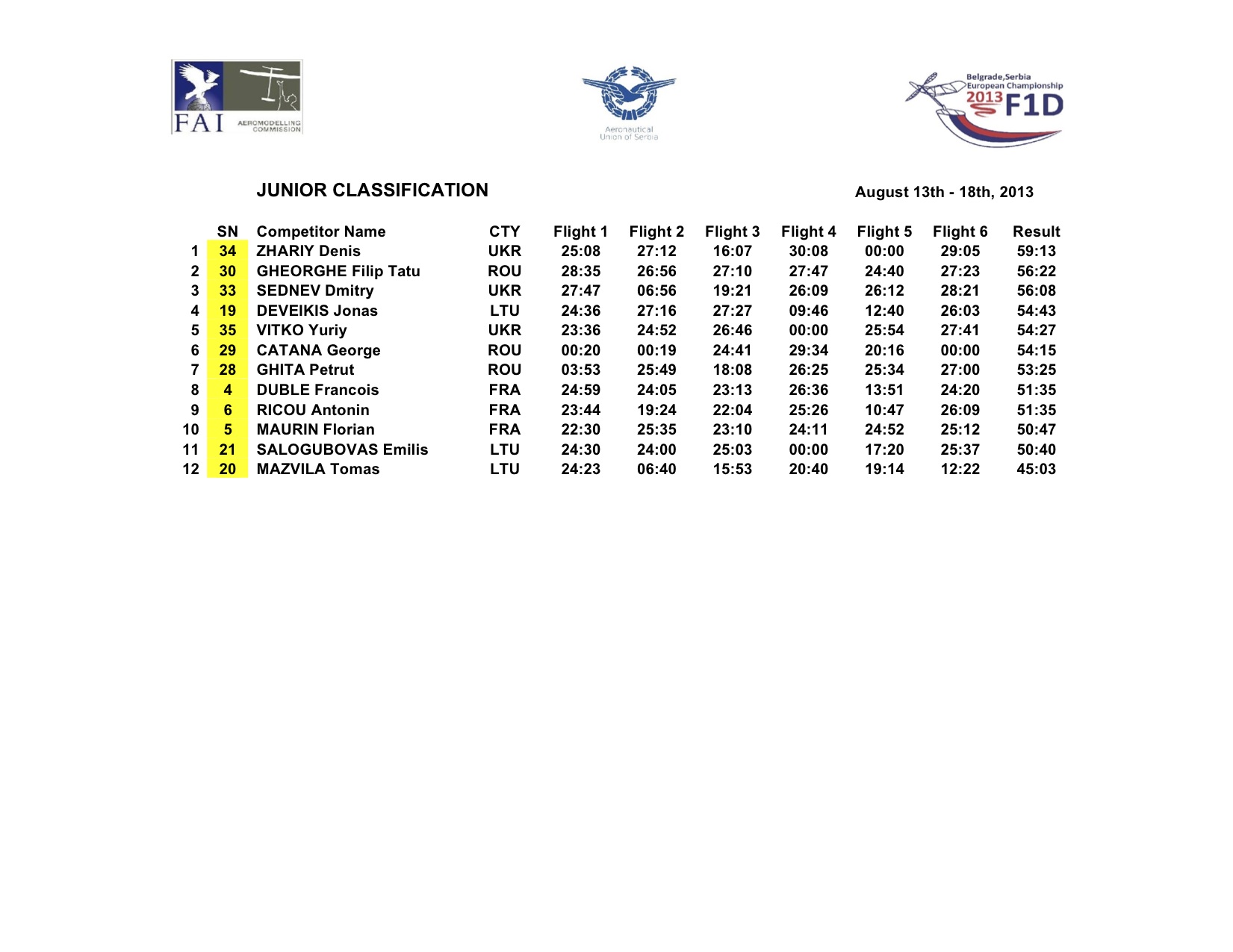
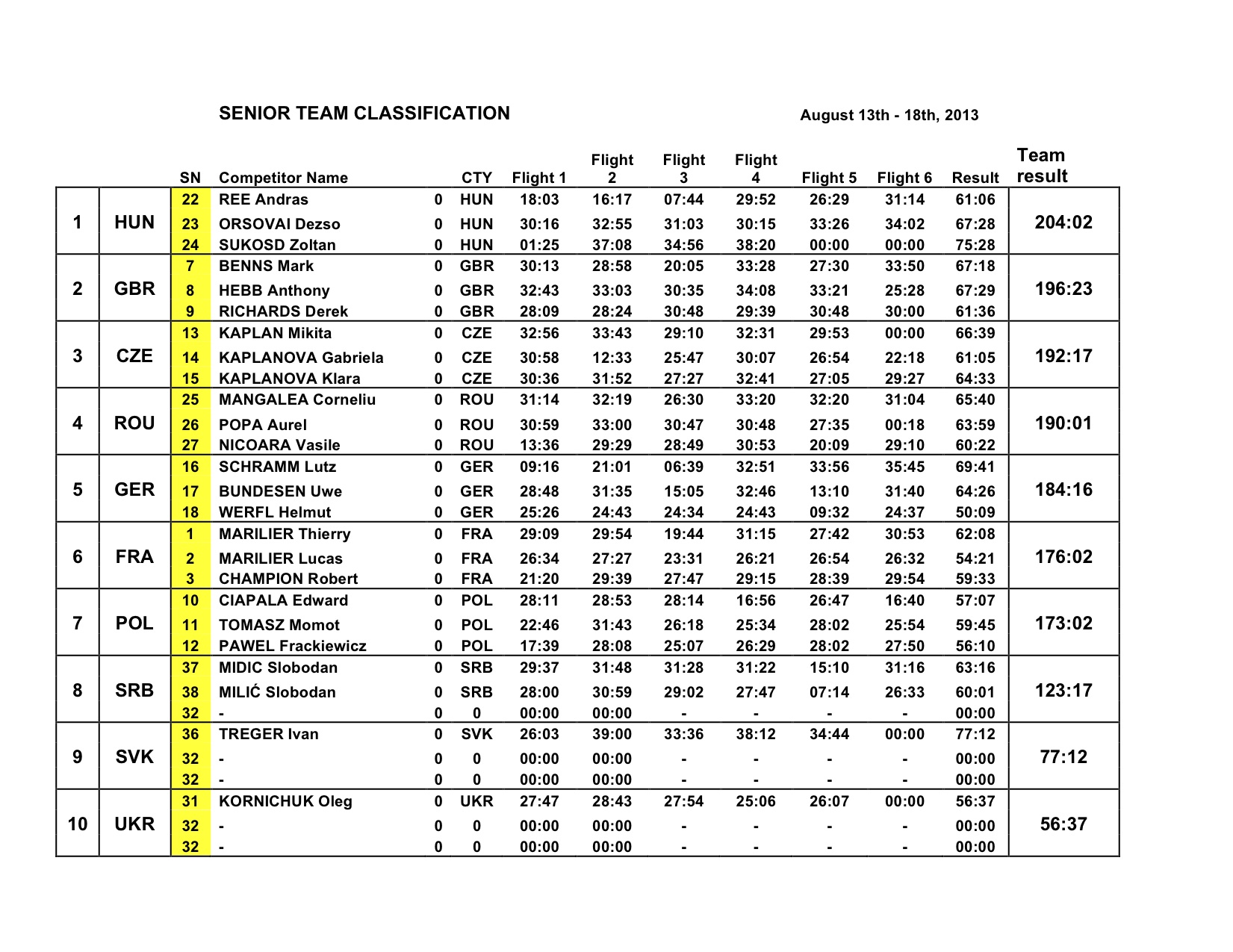
Euro13.1 Euro13.2 Euro13.3 Euro13.4Click here to download a copy of the results. 

Statuses

2013 USIC Reporting by Mike Kirda

In Uncategorized on August 14, 2013 by nicholasandrewray

2013 USIC Reporting by Mike Kirda

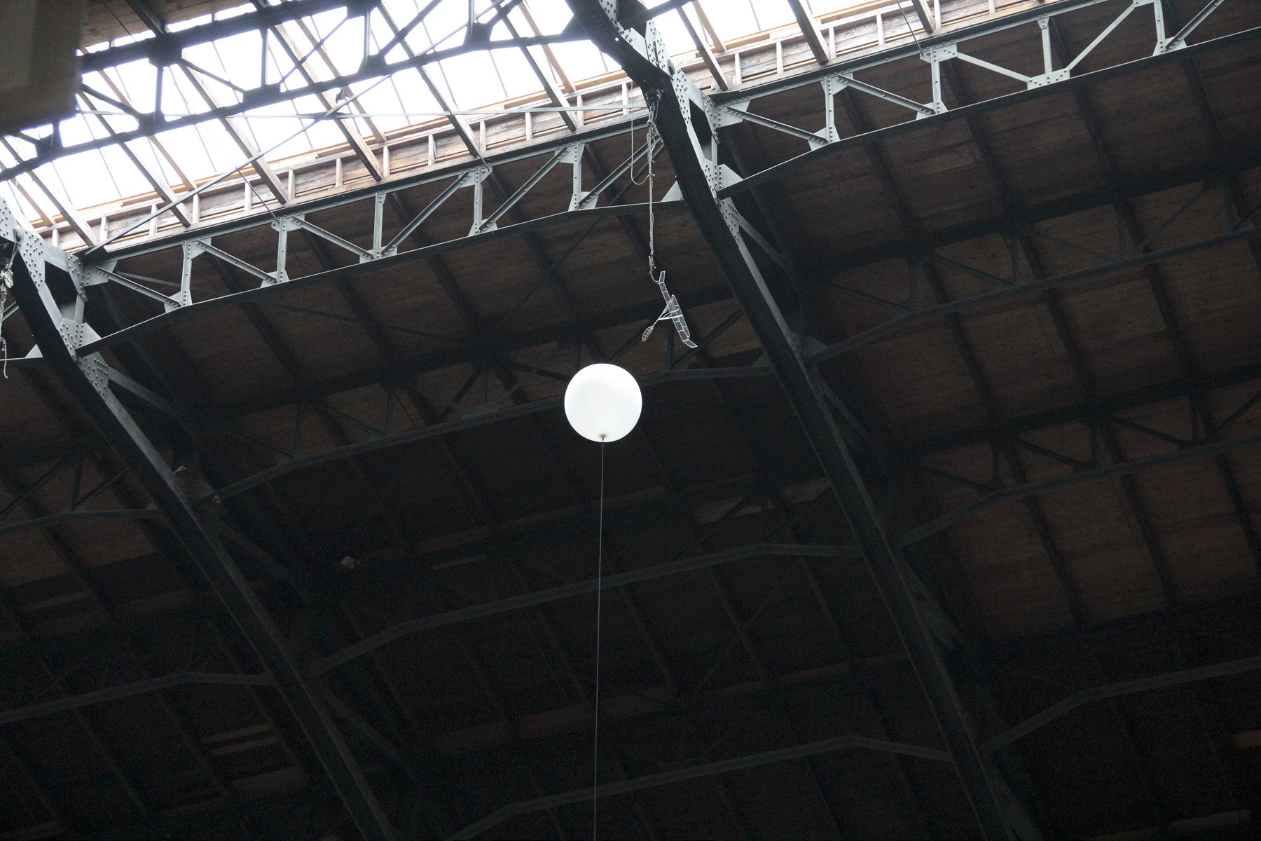
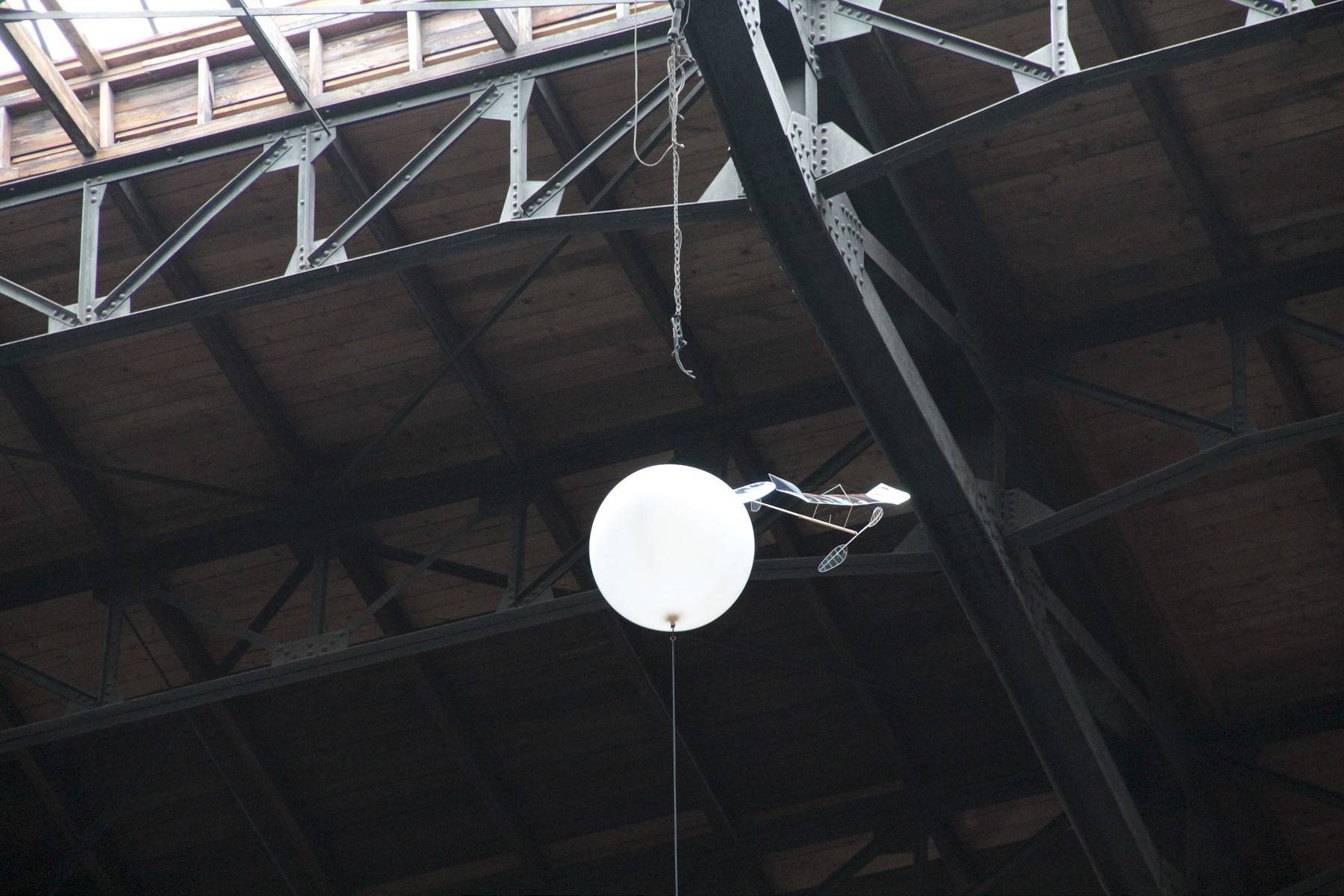
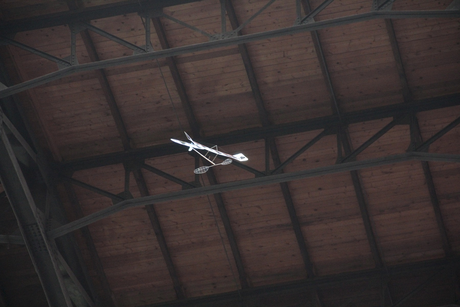
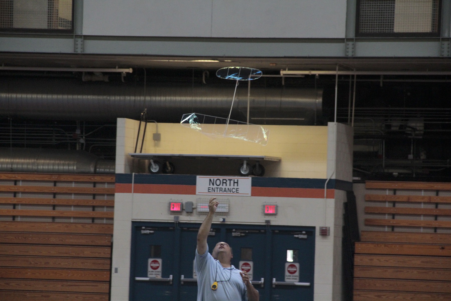
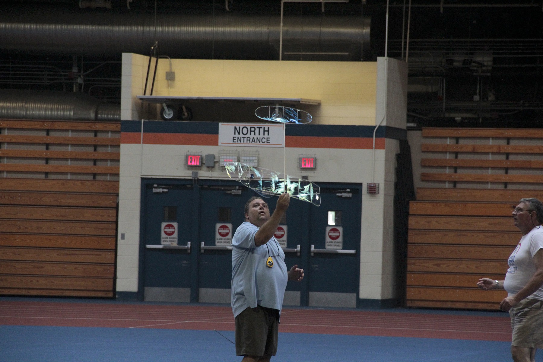
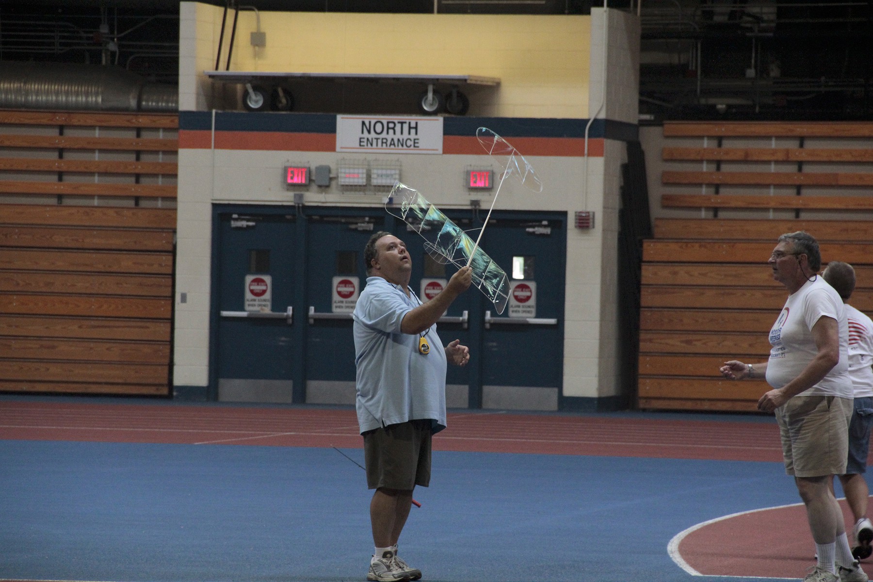
Friday was HLS day and DonS had a beautiful model covered in microfilm.

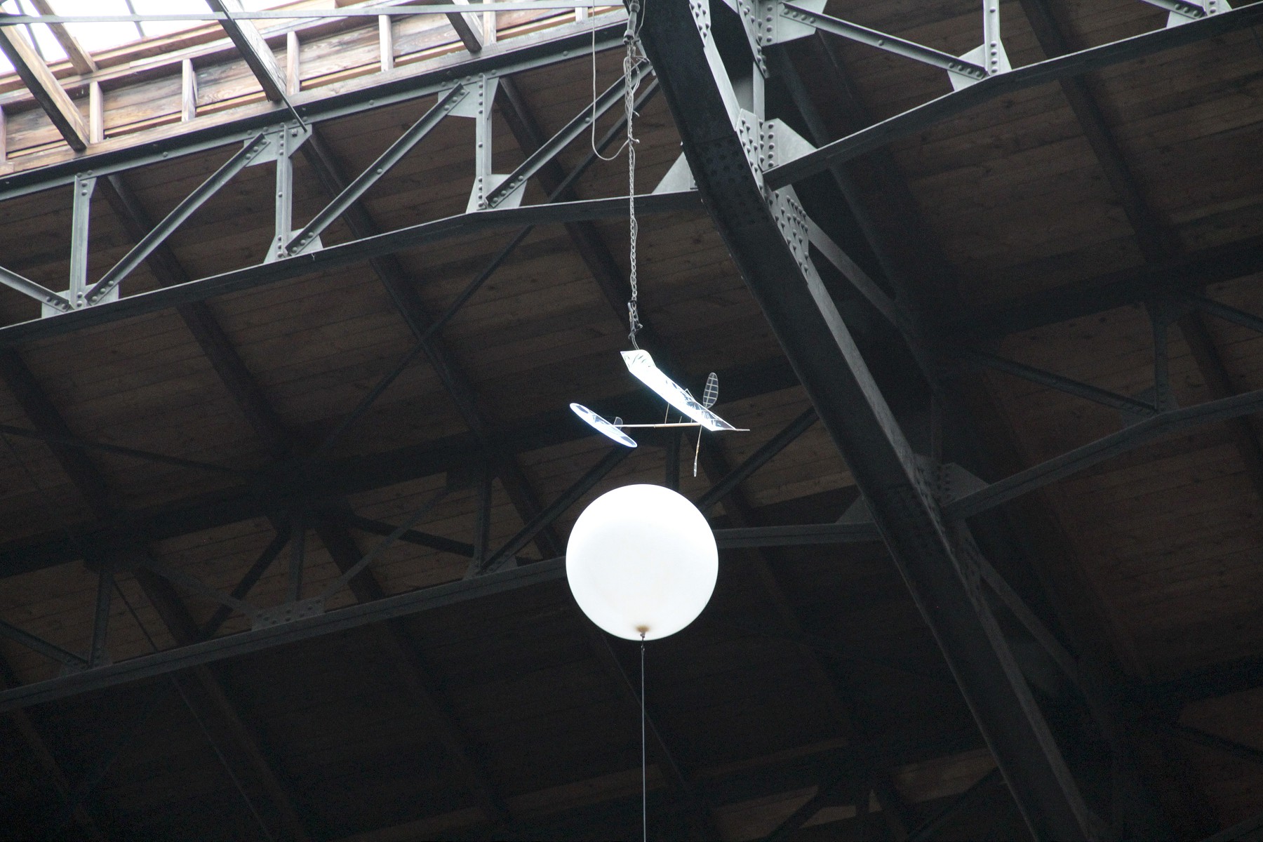
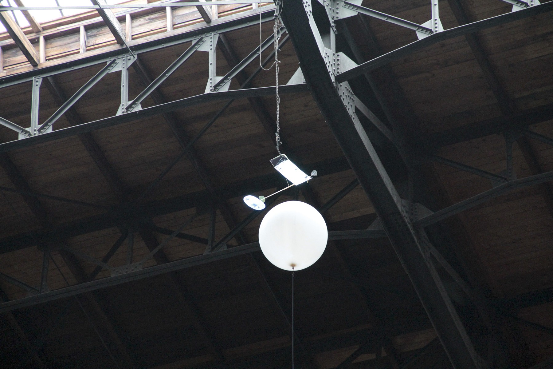
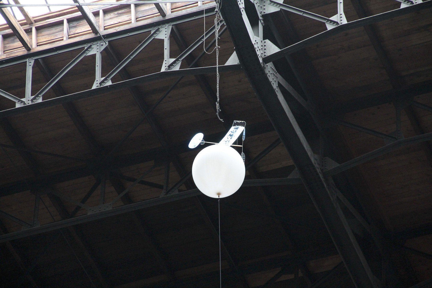
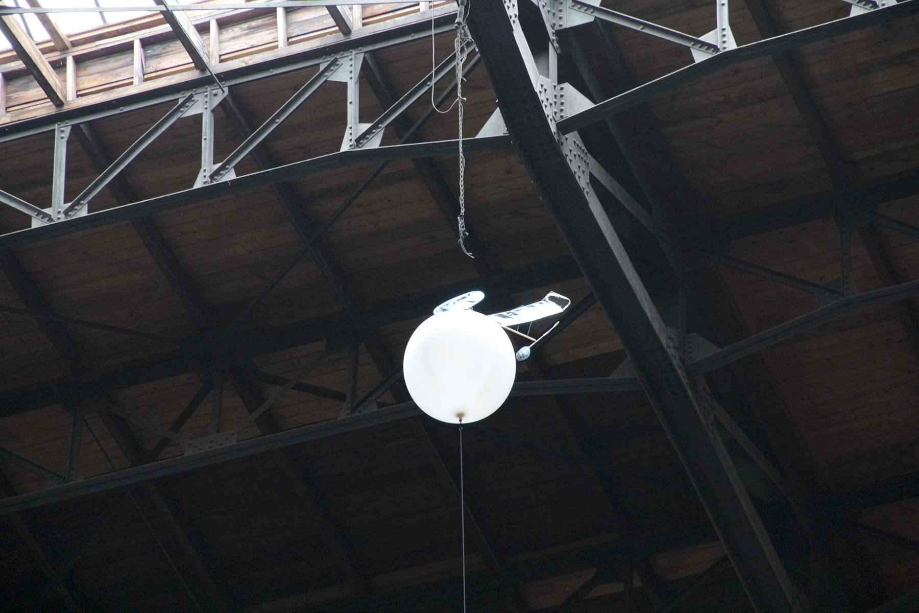
At one point it got hung up on one of the wires or chains hanging from the ceiling. I grabbed my camera and took a sequence of photos as it was successfully recovered with minimal damage to the wing.

_MG_1541-1800 _MG_1542-1800 _MG_1543-1800 _MG_1544-1800 _MG_1545-1800 _MG_1546-1800 _MG_1547-1800 _MG_1547-1800 _MG_1548-1800 _MG_1549-1800 _MG_1550-1800 _MG_1550-1800 _MG_1551-1800 _MG_1552-1800 _MG_1553-1800 _MG_1554-1800 _MG_1545-1800 _MG_1555-1800 _MG_1557-1800 _MG_1558-1800 _MG_1559-1800 _MG_1560-1800 _MG_1561-1800 _MG_1563-1800 _MG_1564-1800 _MG_1565-1800 _MG_1566-1800 _MG_1567-1800 _MG_1568-1800 _MG_1569-1800 _MG_1570-1800

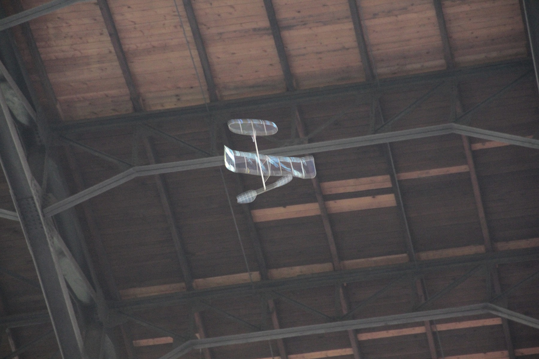
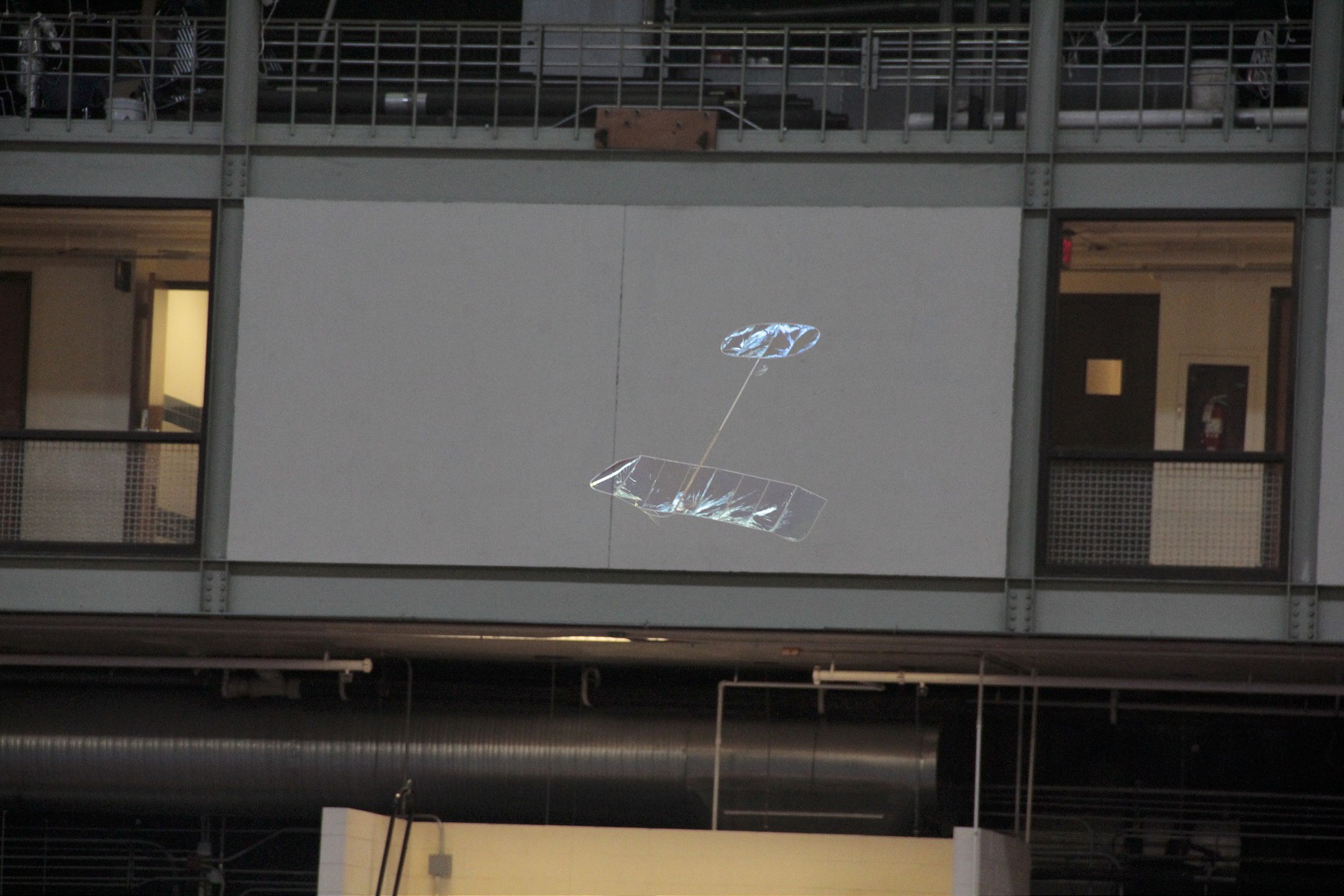
The second sequence we heard a loud SNAP and looked up. The motor on the HLS had snapped and was flailing away. I ran over to grab the camera and started snapping just after part of the fuse/stub/tailboom failed. The model crumbled and came down in a ball.

Within an hour, Don had it glued back together. He had applied a patch of microfilm and the last step was trimming it with the cautery tool. Suddenly it went POOF as the microfilm caught fire. Unfortunately no photos of this exist – but I am imagining him as Wiley E. Coyote. I hope the model is repairable and we can see it next year again.

_MG_1661-1800 _MG_1662-1800 _MG_1663-1800 _MG_1664-1800 _MG_1665-1800 _MG_1666-1800 _MG_1667-1800 _MG_1668-1800