How To Make Your Own Aluminum VP Screws
Nick Ray
October 2013
I started making aluminum M1 x 0.2 (1mm in diameter with a pitch of 0.2mm) screws following the 2012 World Championships. I based my screws on Ivan Treger’s plans published in INAV 125. The screws covered in this article match his specifications as exactingly as I can manufacture them. Ivan told me that he had moved away from nylon screws because they are molded rather than cut. Due to the molding process the threads have tiny mold marks that degrade the threads inside the screw holder as the screw is turned. A secondary advantage is that M1 x 0.2 screws have approximately 127 threads per inch. Compared to a 00-90 nylon screw with 90 threads per inch, it is easier to make fine adjustments. The M1 screws are theoretically slightly heavier than their 00-90 nylon counter parts. However, my milligram scale cannot detect the difference in the finished products. The process of making screws is certainly more time consuming than buying them. Nevertheless, the finished product is more precise and I find a certain charm in making them myself.

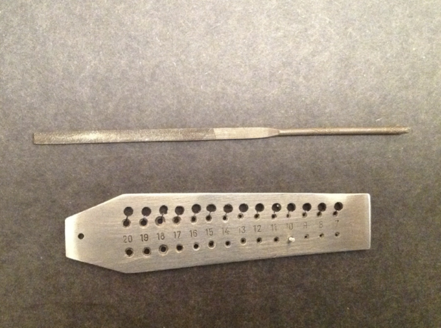
Figure 1: The setup
The smallest diameter machinable aluminum rods I have been able to find to date are from K & S Engineering. They can be found at most local hobby shops in the U.S. and online from various sources. I buy the 1.6mm/0.0625” rods because next size down are too small at 0.8mm/0.03125”. There are three ways that I know of to reduce the rod diameter to the 1mm/0.0395”diameter required for threading. The rod can be drawn, turned or my personal favorite, abraded, to appropriate diameter. I do not have a lathe, and my draw plate is imprecise, so I use the abrasion method described below.
I start by cutting about a 38mm/1.5” section from the rod and placing the section into my keyless-chuck Dremel. I then take a piece of 80grit wet/dry sandpaper and dampen it with cutting fluid. (Actual cutting fluid is great but olive oil works fine too) Then I turn the Dremel on low and sand the rod uniformly along its length down to about 1.15mm/0.045”. Next, I switch to an intermediate 320grit wet dry paper and repeat the process until the rod is 1.04mm/0.041” in diameter. I finish abrading the rod with 2000grit wet dry sandpaper. It is very important to check the diameter frequently and rewet the paper frequently. The cutting fluid helps to reduce heat, which changes the properties of the aluminum and it keeps the sandpaper form becoming clogged.

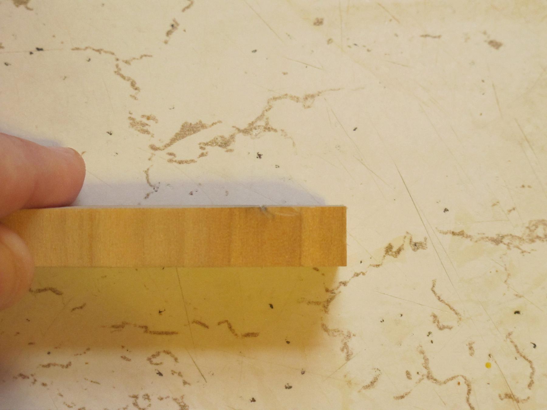
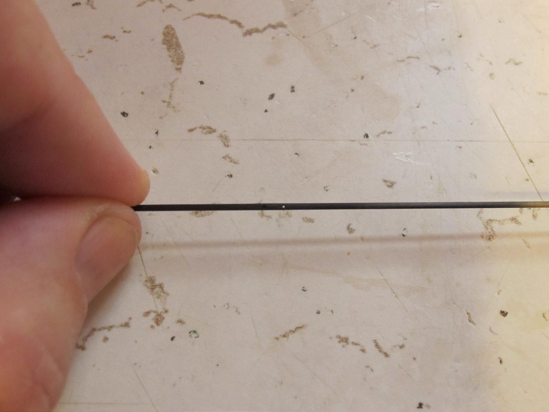
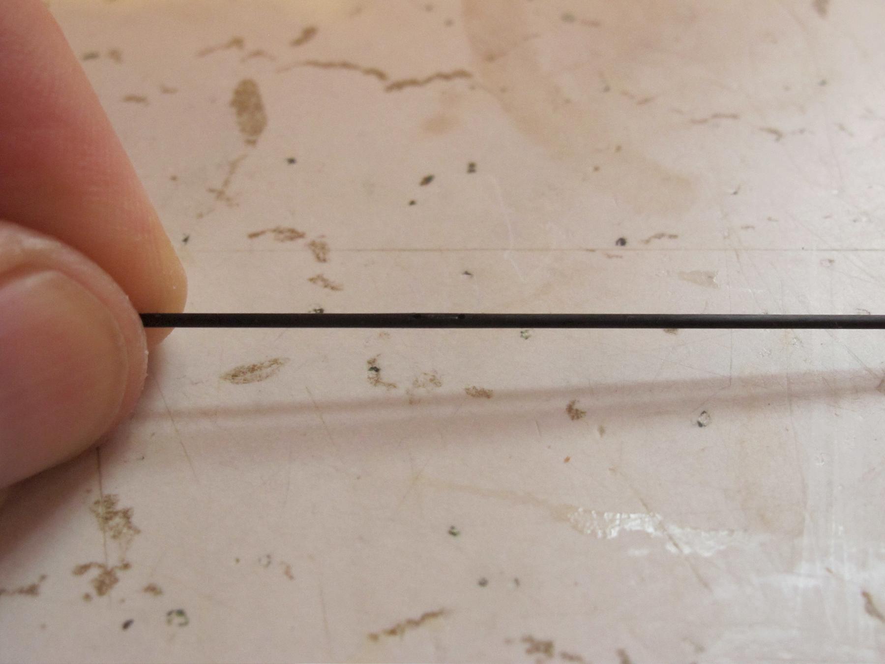
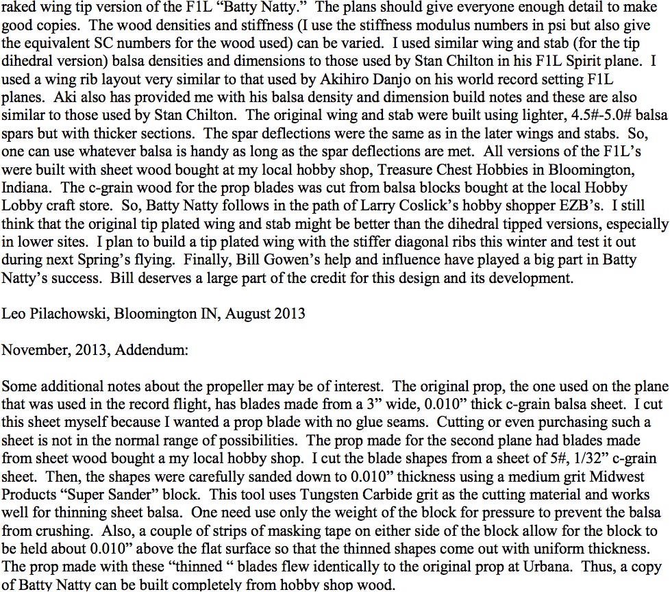
Figure 2: The top piece is a finished rod and the bottom is an oversized piece of original stock
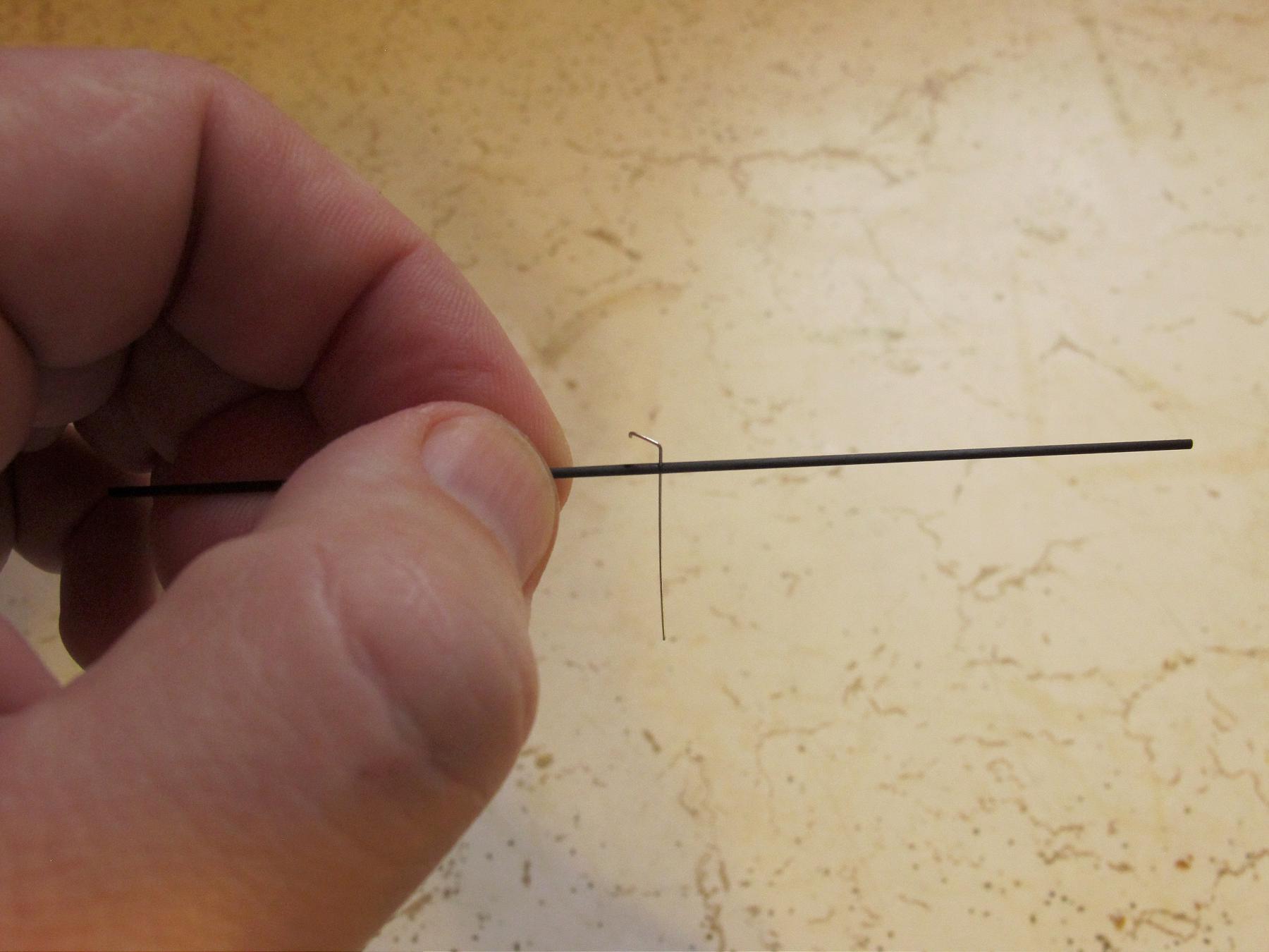
Now that I have the material sized correctly, I cut off an approximately 9.5mm/0.375” long segment and chuck it into a pin vise.

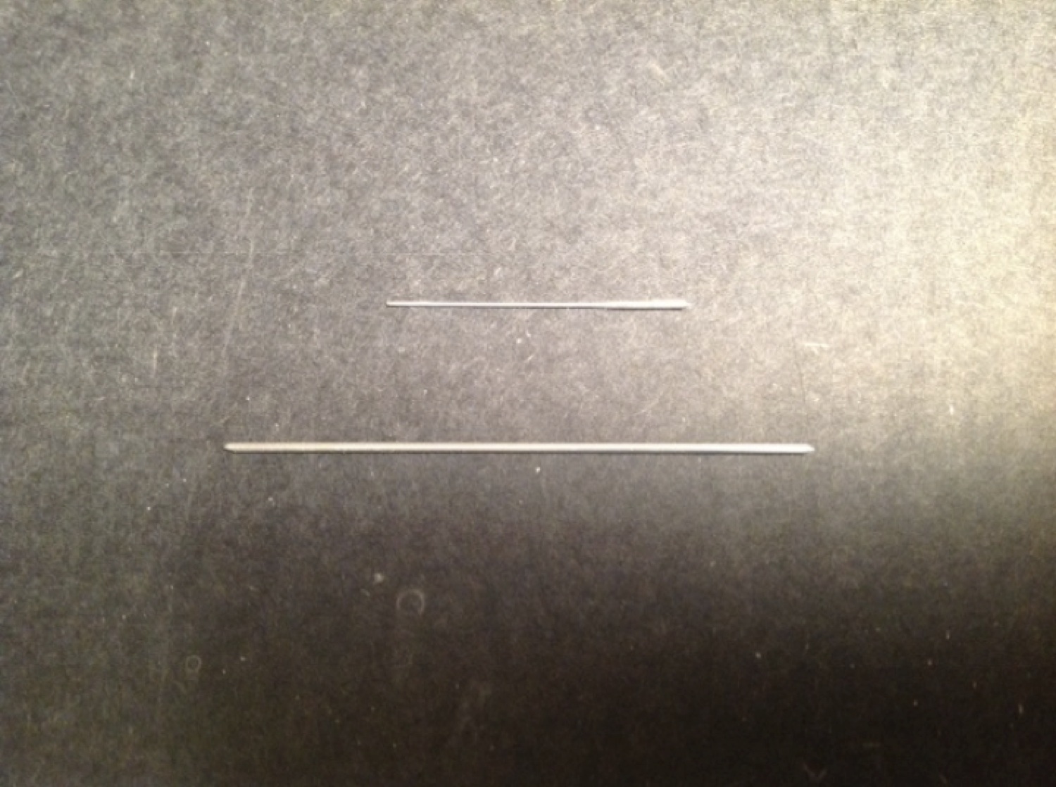
Figure 3: 9.5mm/0.375” x 1mm/0.0395” rod held in pin vise
It is now time to thread the rod. I bought a 15 piece tap and die set made by SE from amazon.com. There are several options available, but this seems to be a case where one gets what they pay for. I would discourage anyone from buying the cheapest options available. The die does not need to be incredibly hard for cutting aluminum threads, but it does need to meet the desired specifications for the screws one wants to make. If the die comes with taps that match the threads it cuts, that is a major plus.
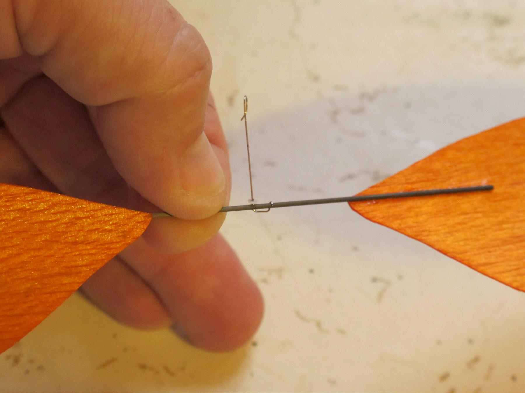
To start, I dip the end of the rod into some cutting fluid and gently turn it clockwise into the die. You should feel rod start to thread. If it does not thread easily check to make sure the rod is sized correctly. My die is not sensitive to burs leftover from cutting the rod to length, though this may be a consideration for some dies. After you have managed about three full rotations, turn the rod counter clockwise to back it out and clean the newly cut threads with cutting fluid. It may help to over lubricate die and wipe off the excess cutting fluid with a rag. Once the threads are clean dip the rod in cutting fluid again resume threading. Keep repeating this process until you have more than enough threads cut to produce a finished screw of your desired length.

Figure 4: An aluminum rod held in a pin vise being threaded into the thread cutting die

Figure 5: View from the bottom/output side of the die.
If you fail to clean out and lubricate the die while you are cutting, the rod may breakoff in the die. Depending on where that happens along the rod, there are a variety of not-so-fun options. The easiest is to cut a slot in the rod and back it out with a screwdriver. If that is not an option, you may be forced to drill through the center of rod, careful to ensure that you do not damage the die, and then clean out the remains of the rod with a tap. If all else fails, buy another die.

Figure 6: Finished threaded rod held in a pin vise
To begin the screw head slotting process, finger thread the rod back into the die. If you have something else that is tapped to match your screw you can use that as a screw holder for this part of the process as well.
First, cut off the excess rod about off about 1mm/0.395” above where the threads stop. Then, using a fine metal file, smooth the top of the screw head. One can either leave a little of the unthreaded rod remaining or file the rod down to the threads as Ivan Treger does. If a portion of the unthreaded rod remains, then the screw will stop before it threads too far into the screw holder to be retrieved. The trade off is there is less usable screw per unit weight than there would be if no unthreaded rod were allowed to remain.

Figure 7: Threaded rod hand threaded into the die for making the screw head

Figure 8: Threaded rod with the top of rod filed smooth
After what will become the head of the screw has been filed satisfactorily smooth, visually divide the top of rod into two equal parts. Use a single edge razor blade to score the top of the rod in the middle. This score mark will guide the saw when starting to cut the slot in the head of the screw. If your score mark is not perfectly centered then polish it away and try again. I make the heads of my screws first so that I do not have to worry as much about my screw coming out too short if it takes more than one try to get this step correct.

Figure 9: Scored screw head
Next use a fine Zona or jewelers with about a 0.2mm/0.008” kerf to cut a grove 0.5mm/0.02” deep into the head of the screw. Lastly polish off any burs remaining on the head of the screw with a fine metal cutting file.

Figure 10: Head slotting saw

Figure 11: Finished screw head
The screw now needs to be filed to the appropriate length. The finished length of your screw will depend on the design of your hub. The rule of thumb that I like to use is when your low and high pitch screws are turned completely in, they should stop the prop from changing pitch. The spring screw should be long enough that when it is turned completely in, the spring should be at its maximum range of travel. If you are following Ivan Treger’s plans this will mean that your high and low pitch stop screws will be 2.3mm/0.091” long and your spring screw will be 3.5mm/0.138” long.
I use a fine metal file to size the screw to the desired length. It is critical that the finished screw bottom be perfectly flat. If it is not, adjustments will be inconsistent as the screw is turned. It may help to visually line the file up parallel to the die. Turn the screw periodically to make sure that while the screw is flat when looking at from one direction, it does not become uneven from another.
If you are making a low or high pitch stop screw, you are now done. However, if you are making a spring screw there are still a few steps remaining.

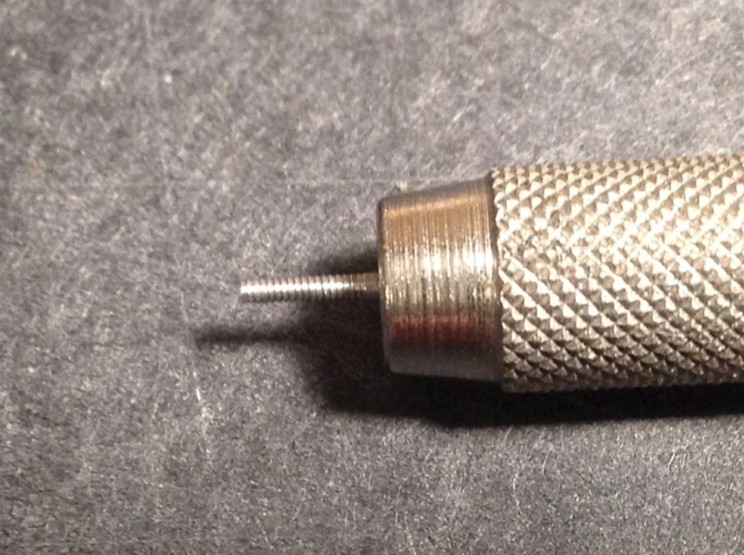
Figure 12: The bottom of the screw after filing it down to the appropriate length
To being making a hole for the terminal end of the spring, first locate the center of the screw and use a pin to score the center so that the drill bit does not wander. Then use a 0.4mm/0.0157” drill bit to make a hole 1mm/0.0395” deep into the center of the screw. I have found it helpful to place a drop of cutting fluid on the tip of the drill bit once I get the hole started, to reduce friction and to keep the screw from backing out of the die. Take care to keep the drill centered so as not to destroy the screw or the die. Finish the screw by gently polishing off any burs on the bottom of the screw with a fine metal file.

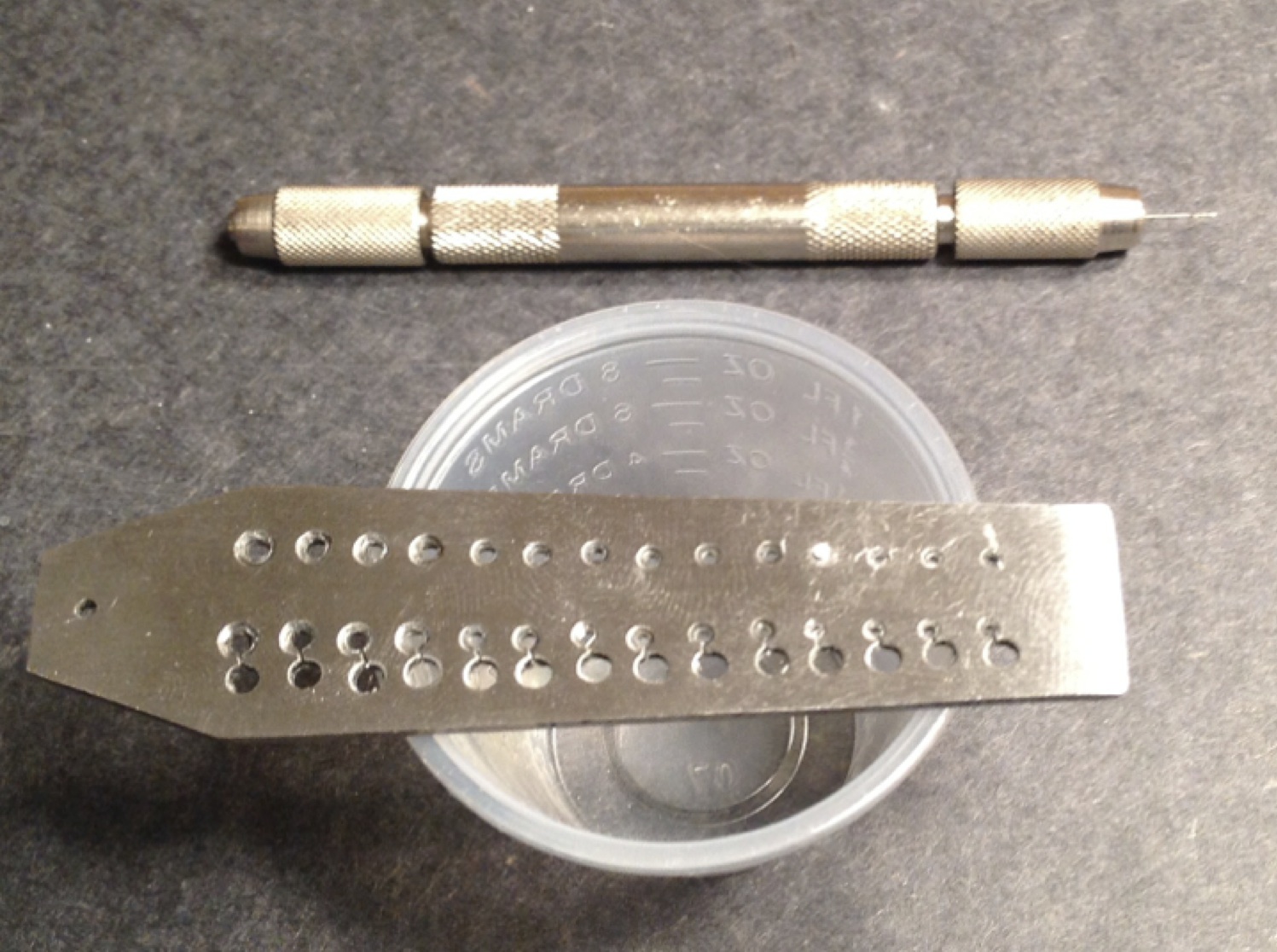
Figure 13: Bottom of spring screw and scoring pin

Figure 14: Pin vise with 0.4mm/0.0157” drill bit

Figure 15: Finished spring screw viewed from the bottom

Figure 16: Finished screws: spring screw on the left and low and high pitch stop screws on the right