
Because we’ve all been there
They say it takes a gallon of water to grow a single almond, and sometimes it feels like it takes a pound of rubber to cut a single motor to the right linear density. I think many indoor modelers know this plight, especially if you fly classes with a rubber restriction, or you as a modeler just like to maintain a fixed motor weight with any class you fly. So what do you do with all this left over rubber? Spaghetti? More new airplanes to use all that left over rubber? Preferably, you’d want to cut it right the first time, and this article details the methods I use to precisely cut rubber to the right density after many years of trial and error.
Before I dig into how to precisely cut rubber, I think it’s necessary to explain why. For decades and throughout many classes of indoor free flight models, it was, and still is, customary to compare motors to each other using a thickness measured from calipers to tell the modeler whether the rubber can deliver enough power and enough turns to the model to fly it as intended. This method has been deemed tried and true for many years by many indoor modelers. But then came the rubber restriction rules, and the need to squeeze every bit of performance out of the rubber motor became even more critical. As the rubber motors on a standard F1D got thinner and lighter, it became clear that the tried and true method of comparing rubber using thickness was starting to fall out of favor. Many flyers have since started to convert over to a linear density measurement, by which a set length of rubber is weighed, and an “average” weight per unit length is measured and used as a comparison. From one of my recent rubber cutting sessions, I plotted the strip number, which is just strips cut consecutively from the same bag/strand of my rubber batch, versus the actual cut rubber thickness for a consistent linear density. Notice that the thickness varies by almost 0.002″, or 0.051mm. Through tests I’ve found I can get just over 1322 turns in an F1D motor at 31.5 mg/in and we will then compare that target amount of turns with rubber cut using the thickness method. For this thought experiment, I’m choosing a target rubber thickness of 0.051″ to as closely as possible represent the 31.5mg/in rubber density. Using the variation in the chart below, and my handy-dandy turns versus rubber density table, I find that the lightest motor cut to 0.051″ (31.5mg/in X 0.051 / 0.052 = 30.9mg/in) will give me 1361 turns and the heaviest motor (31.5mg/in X 0.051 / 0.050 = 32.1mg/in) gives me 1291 turns. This is almost a 1:30 difference in potential flight time for an F1D! It’s clear we need a way to reliably and consistently cut the rubber to the right linear density. For competitive F1D, it is often required to be able to cut rubber down to a precision of about 0.3 mg/in (11.8mg/m).

Now to get onto how to cut rubber down to ±0.1 mg/in. Below follows a step-by-step guide for my process and some notes to keep in mind when setting up this process for yourself.
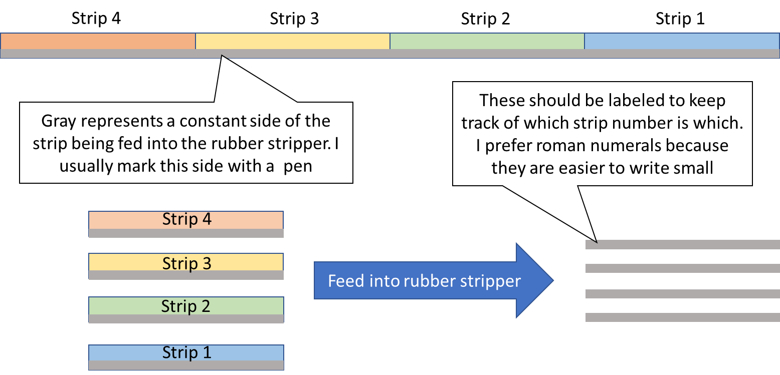
- Calibrate your rubber stripper. For my cutting, I use a Johnson rubber stripper because the entire feed moves with one dial unlike a Harlan stripper that requires both dials to be moved to adjust the feed. While I do believe this stripping method can be setup for a Harlan-type rubber stripper, my article mainly focuses around the method itself, and a few things might need to be tailored to make this work with a Harlan stripper. When calibrating your rubber stripper, I take 4-5 consistent lengths of rubber of enough length to get an accurate mg/in measurement using a scale. For my purposes, I use 5 inch (127mm) long strips. DON’T SKIP THIS STEP! At this point, you may be thinking “Hey I’m wasting about 20 inches of rubber just for calibration?” Don’t let this thought fool you, because as long as you don’t adjust the feed width again, you likely only need to do this step once, and then recheck the calibration for the next time you need to strip rubber for a contest. You have to recalibrate any time you use a new batch of rubber that requires you to change the width of the feed on the Johnson stripper. Before I start stripping, I record each of the strips weights in a spreadsheet , number them, and use a pen to make an arrow on the strip to keep the feed direction constant in the rubber stripper. After initial recording, I cut the strips to several different dial settings that I believe will cover the range of rubber densities I want to strip from. Note: Backlash in the worm gear is very critical! When adjusting your rubber stripper, make sure you are adjusting the feed in one direction only. For example, I always adjust the dial towards smaller settings. If I need to adjust the dial to a larger setting, I make sure to back out the dial a few ticks more than required (say 0.005″), and then back it in to the dial setting you want. This will ensure the feed is sitting on a consistent side of the worm gear and minimize backlash associated error.
Now that I have my strips cut and weighed, I enter those numbers in my spreadsheet (I have my spreadsheet attached to this article), and then create a plot of Dial setting versus Actual (cut) thickness. This will then be used to preset the dial for each rubber strip individually based on their variance in weight. The blue equation shown to the right of the graph below is the calibration curve that can be used to calculate dial setting from actual thickness.


2. Precut all rubber to desired length. This process is fairly straight forward, just use the diagram in Figure 1 and cut all the rubber to the desired lengths in the same way that is done for the calibration. I use 14.00in (35.6cm) strips for F1D full motors, number them, draw an arrow to indicate feed direction, and weight them. I enter these numbers into the dark yellow boxes in my spreadsheet as seen below. The spreadsheet then calculates the dial setting in the light red box. The equations I use to calculate the dial setting can be seen below. The result is the dial setting needed to cut the rubber to the right density shown in light red in the figure below.
Raw Strip Density = Raw Strip Weight / Length
Target Strip Thickness = Target Density / Raw Strip Density * Raw Strip Thickness
Dial Setting = SLOPE * Target Strip Thickness + INTERCEPT
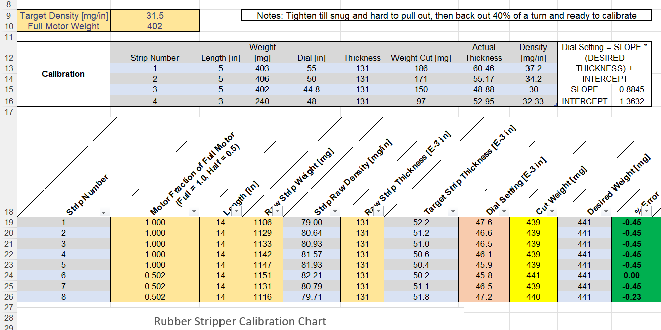
3. Strip the rubber and weigh the final cuts. I have a filtering tab on my spreadsheet that allows me to easily pick each strip from the largest dial setting to the smallest dial setting, set my dial appropriately, and then strip the rubber while only adjusting my dial in one direction. I weight the final result and calculate the final rubber density as seen in the green columns below. And behold! Eight strips of rubber within 0.1 mg/in of my target of 31.5 mg/in

If you have any questions, feel free to reach out to me at ameg3237@gmail.com.
~ Emily Guyett
Rubber Stripping Spreadsheet Tool (Compatible with Google Sheets)


Thanks for publishing this! Will take me some time to work through your method.
Absolutely! Yeah it’s quite a process but if you have any questions by all means reach out