Archive for the ‘Uncategorized’ Category

Statuses

Boron-capped prop outlines

In Uncategorized on January 7, 2013 by propblocks

Boron-capped prop outlines


Many of the top fliers in F1D are using carbon outline props. One of the drawbacks to using carbon is the sanding required to get down to weight. This is what drew me to towards boron-capped prop outlines.

For this example, I used standard 0.025″ 5# balsa cut into squares. I like using several reference marks to keep the grain straight and ensure that there is no twist introduced. Because many of the steps are the same as building a standard built-up prop, not every step is illustrated.
Prop outline with flat ribs attached

Prop outline with flat ribs attached

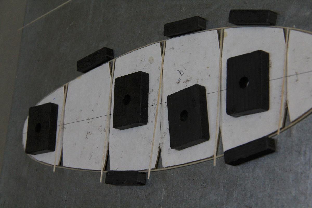
I build on a piece of steel with magnets. The larger ones hold down the forms, the smaller ones are used to keep the balsa in place. Here instead of using sliced ribs, I used flat pieces. First, I glued all the ribs to one side of the outline.

Outline with all flat ribs attached

Outline with all flat ribs attached

Here, all of the ribs  are glued down. The ends are left loose and trimmed.
Attaching boron

Attaching boron

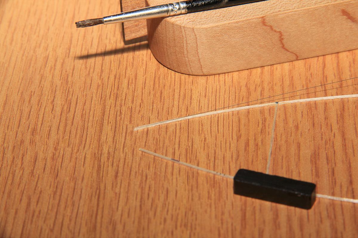
Next, the boron is attached here with a brush dipped in acetone. A bit of thinned Ambroid could also be used to ensure attachment at the end.

Attaching boron

Attaching boron #2

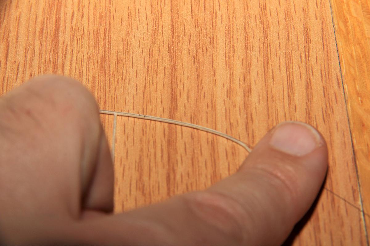
I use my  fingers to align the boron and hold it down. Then I  brush on more acetone to attach the boron. The brush should be pretty ‘wet’. Just be careful around the rib glue joints. It may be useful to mark the rib joints in case they come loose.
Attaching boron

Attaching boron #3

Once you get down to the tip, work in smaller sections. Thinned Ambroid can also be useful here at times. Keep working in small increments, just 1/4″ at a time or so.

Around the tip

Around the tip

I try to keep the boron as centered as possible – Keep working in small sections here.

As the radius gets smaller...

As the radius gets smaller…

It becomes easier again and you can do an inch or two section at a time.

Capping the ribs

Capping the ribs

I’ve used 004 boron for the inner two ribs here as the spar will not go to the end. Not sure it is necessary. I have the boron slightly overlap the glue joint to give some extra strength. Thinned Ambroid helps here occasionally. An Xacto blade can be used to ‘break’ the boron at a particular place – just bend the boron against the blade until it snaps. I don’t tend to get fragments this way, but if they do occur the glue on the boron typically holds them in place.
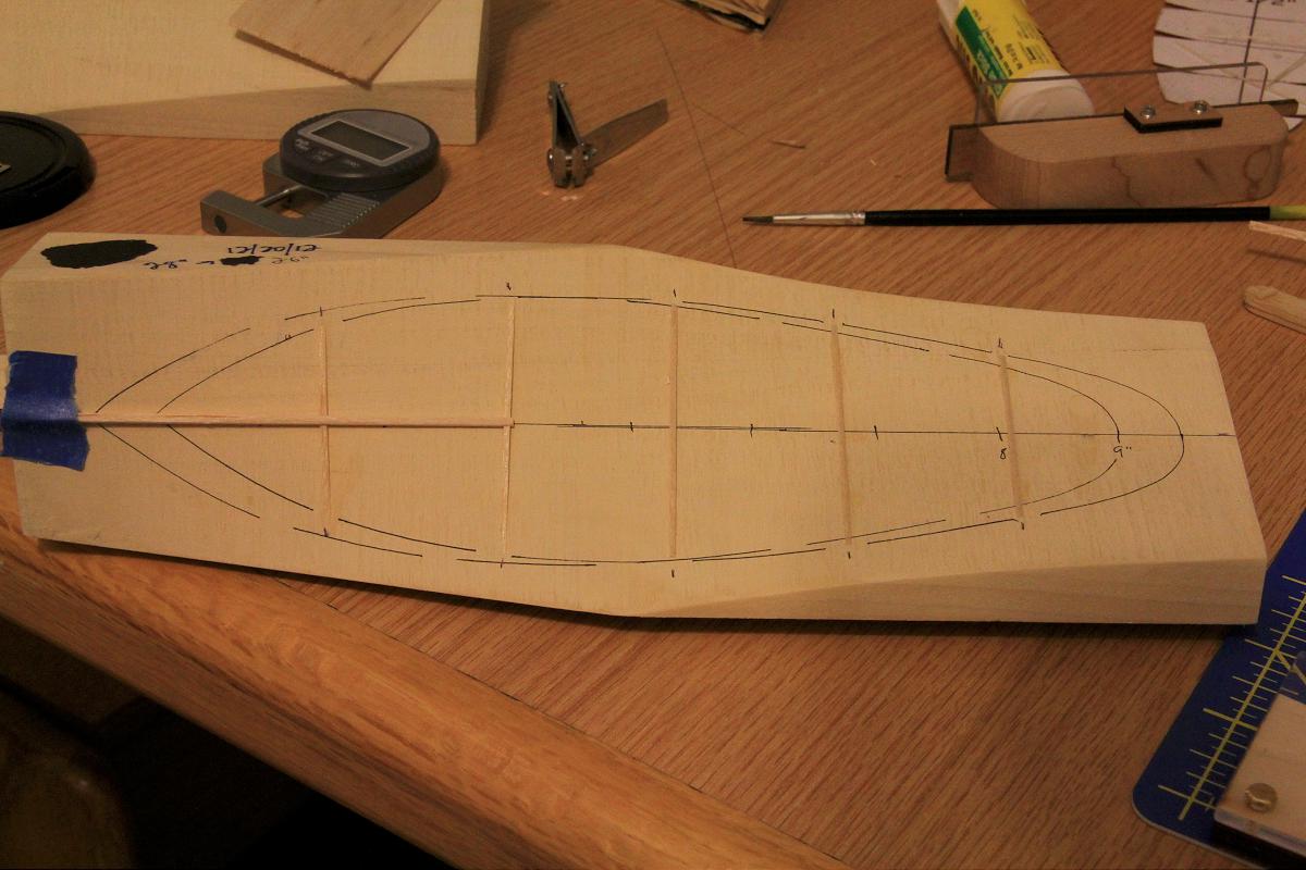
Preparing the prop block

Preparing the prop block

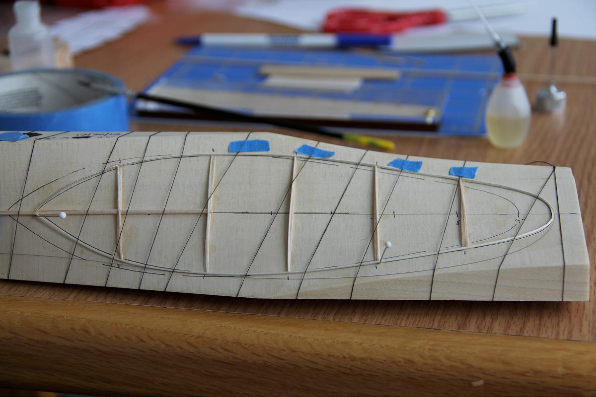
Pictured here is a prop block I cut on my fixture. I have marked both the outline and the rib locations and cut out some 3% arc sections, gluing them to the block with thinned Ambroid. On the inner two ribs I cut a bit out to hold the spar in place. The spar stands slightly proud here, so 5% might be better here.

Not pictured – The entire outline is placed in a tray of water and soaked for several minutes. It comes out all bent as the balsa expands.

HINT: It might be wise to use some wax or Scotch tape on the line of the outline before this next step.
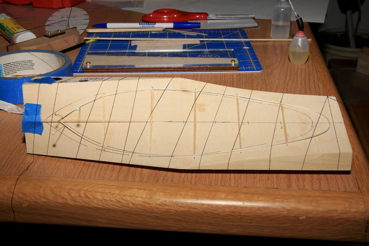
Thread wrap wet outline

Thread wrapped wet outline

Place boron side down, adjust to the line and wrap with thread. If there appears to be any lifting off the block, add bits of tape to the thread right next to the outline to keep it tight. Secure the end with tape. I like to use thin silk pins, because they press pretty easily into the Poplar block. You typically just need them near the spar/outline joint. Let dry thoroughly – best not to use heat (oven) here.

Slice ends of outline off

Slice ends of outline off

This one is not as in focus as I would like but a bit of boron is sticking out past the angled slice. Insert the boron into the spar wood being careful to align the top of the outline with the top of the spar. This is one of the most fiddly bits. Glue it up well and let dry.
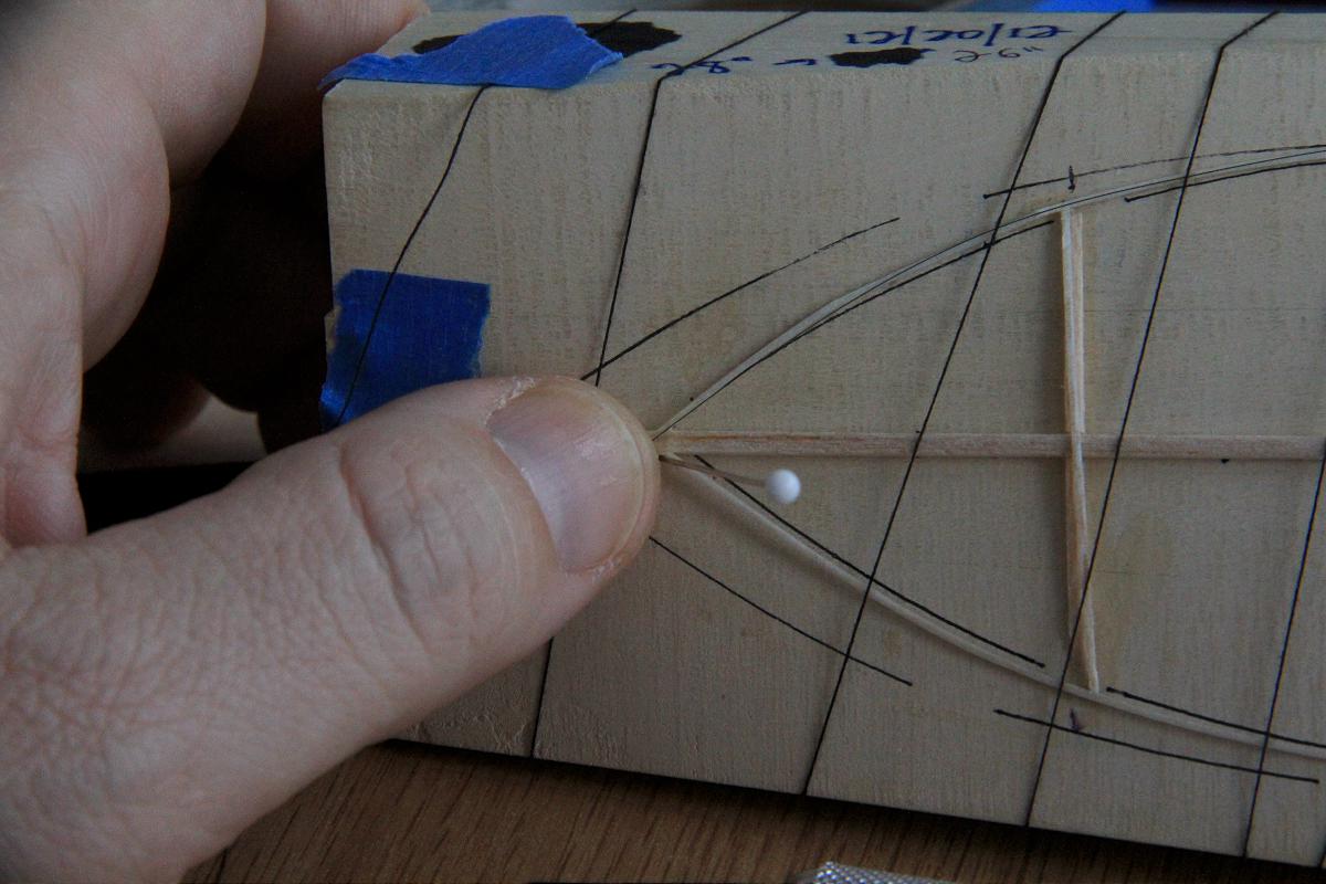
Attaching boron on top

Attaching boron on top

Now we have to repeat the process attaching the boron on the top side. First, slide the boron underneath all the threads at  the top. Bend it down so it approximates the arc of the outline and glue well here. It will overlap the spar/outline joint. Use thinned Ambroid if necessary to glue it down here.
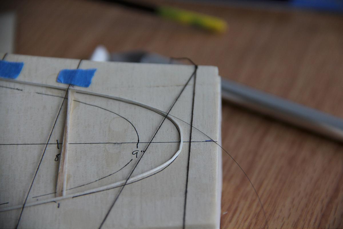
At the tip

At the tip

The rest is amazing similar to doing the bottom side. Brush on acetone while holding the boron in place. When you get close to the tip, loop the boron around underneath the lower threads.
Starting on the bottom

Starting on the bottom

Pictured above, is the outline with boron looped underneath and ready to begin gluing.

I omitted taking pictures capping the ribs. I found it best to start at the top with some thinned Ambroid, let dry thoroughly, then bend the boron to the rib outline and use the brush dipped in acetone to attach it.

Be careful when separating the outline from the block. A thin razor blade can be useful if you happened to accidentally glue it to the block.

At this point the blade can be covered normally. I have not had any problems with the boron popping loose to date. If it does occur, a bit of acetone should reactivate the glue – or it could be glued down with very thin Ambroid.

I suspect that the 5# 0.025″ is too heavy in this application. I would try some 4# 0.020″ wide (keeping the distance between boron at 0.025″) to lighten the outline. I assume the ribs could also be done somewhat differently to shave some weight.

Two last points: All boron was 003 except for the top/bottom of the two innermost ribs. I cleaned the boron with paper towels dipped in acetone first, then used one of Ray Harlan’s glue pots to apply the glue ahead of time. I will typically do 10 or so boron this way and leave them taped up to the wall until needed.

Source: http://www.indoorspecialties.com/contents/en-us/d40.html

Ray's glue pot

Ray’s glue pot filled with Ambroid

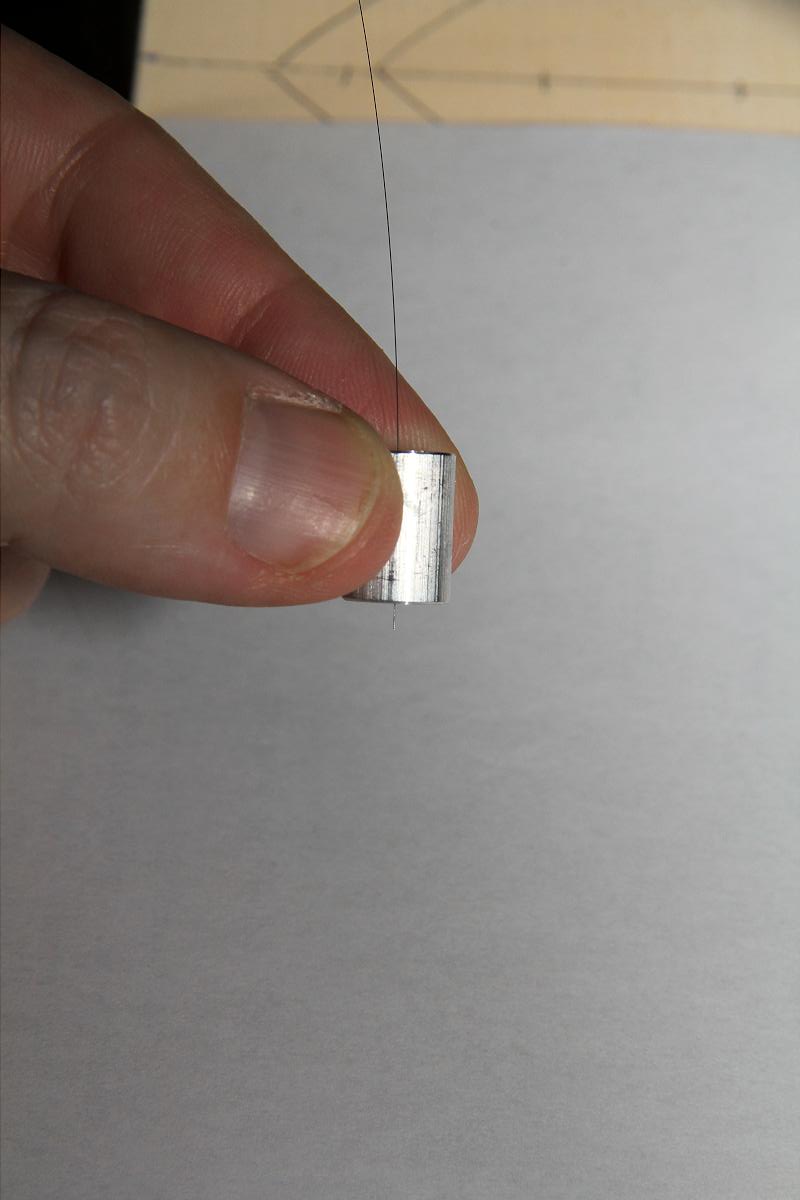
Boron inserted into glue

Boron inserted into glue, sticking out the bottom hole.

Take good care of the glue pot, soak in acetone when needed. A 0.013″ wire will help keep it clean.

Hoping you find this helpful!

Mike Kirda

Statuses

Forty Minute Club

In Uncategorized on January 7, 2013 by nicholasandrewray

Forty Minute ClubTo download a copy please click: 40 MinuteClub 2012

Statuses

A2Z Balsa Stripper Review by Mike Kirda

In Uncategorized on November 6, 2012 by nicholasandrewray

A2Z Balsa stripper

The stripper itself comes with two micrometer head assemblies, a bar of aluminum, a length of self-healing mat, a blade holder, one sealed straight scalpel blade and a copy of instructions. The buyer is to provide the base. I used a bit of ¾” light MDF as I had some leftover from building my model bench.

The base was sliced about 7” wide by 24” long. I vacuumed the top surface and attached the self-healing mat using the tape provided. Attaching the micrometer heads was a matter of lining the head up to the bottom, then using the two screws to mark the pilot holes. I drilled them out using a cordless drill and attached them to the base with the provided screws. So far, everything is great.

I proceeded to extend the micrometer heads out fully. One extends easily, the other does not. I grabbed a bit of silicone grease and spread it onto the threads. After a full retraction and extension again, there was very little change in the feel. I proceeded to remove the assembly and remove the threaded rod entirely. Looking inside, I could see that the threads were not as clean as they should be. Luckily I had the correct tap, ¼” x 20. A quick full tap in and out and some of the plastic came right out. I cleaned up some of the edges with an X-Acto blade and then reassembled the unit adding a bit of silicone grease again. This time the micrometer moves easily. Using a tissue to clean the grease, I grabbed the threads lightly and extended the rod fully.

Attaching the blade is simple, provided you have the needed 5/64” hex driver. It would be better if A2Z provided one. I used a Candidius blade sourced from A2Z. Truing up the side on a sheet of balsa, you can sight down the edge of the aluminum straightedge. Back off both heads three full turns, move the straightedge, then draw the blade along the edge. The feel is smooth and almost effortless. The resulting edge is smoother and straighter than anything you can achieve with a normal Master Airscrew stripper.

Pros:

  • Inexpensive and works very easily after a bit of cleanup.
  • Blade holder works very well.
  • Tapers are easy to make.

Cons:

  • No hex driver provided.
  • Mat has tape on it and this produces bumps in the surface. The mat without tape on it would be better. If you are not careful in placement of your wood, the blade holder can ride at an angle and provide perfectly trapezoidal cross-sections. 

Hint: Make more holes so you can position the micrometers exactly where needed. It is easier to cut 9” tapers when the micrometers are 9” apart. 

Mike Kirda 

Statuses

In Uncategorized on October 30, 2012 by nicholasandrewray

From the Editor’s Desk:

From 1960 to October of 2012, the newsletter was distributed via print media several times a year. Over the years, too many people to name have supported INAV by providing editorial and publishing services. However, the strength of INAV has always been its content, which is provided by its readers. Beginning in November of 2012, Indoor News and Views will switch over to a web-based format. Much of what the indoor community has come to love about INAV will remain the same. Nonetheless, there will be a few changes that I hope will make the newsletter more informative and timely, and will simultaneously reduce the cost associated with its production.

The content of INAV will continue to be generated by its readers. The submission process is now somewhat more streamlined. To submit an article, simply follow the instructions on the submissions page. All submissions will be reviewed  by an editor with some knowledge of the content being submitted. Once the article is approved for publication, it will be posted to the blog section for everyone to read. Once we have 40 pages worth of new content I will compile a new INAV issue and post it in the download section. Thus, it will still be possible for anyone who wants one to print a PDF of the issues.

Other changes that will affect INAV have to do with the new functionality of web based publication. We will be able to offer contest announcements under our events section. The events postings will be updated in a timely manner, thereby resolving INAV’s historical problem of publishing the contest announcement and results in the same issue. Also, we now have the ability to allow comments on the content we publish. There has been some concern expressed about ensuring that all of the comments posted are constructive and polite. For the time being, I am trusting INAV’s readership to conduct itself accordingly. However, if I am given cause, I will remove the comments feature from the blog. Last but not least, INAV will no longer be charging subscription fees. The web based format is much cheaper to produce and maintain. Therefore, INAV can now be sustained with occasional donations from its readership. Thank you to those of you whose donations have made the continuance of the newsletter possible all these years.

I now invite you to start writing and drafting content. Without your submissions there is no INAV.  I will try to keep my meanderings about the business of INAV to a minimum from here on out so that we can start enjoying reading about our hobby again.

Regards,

Nick Ray